Introduction
This manual provides detailed instructions for the installation, operation, and maintenance of the SINOTIMER PID Temperature Controller Kit 25DA. This intelligent temperature control system is designed for precise temperature regulation in various industrial and scientific applications.
The kit includes a PID temperature controller, a 25DA Solid State Relay (SSR), a K-type screw thermocouple, and a heat sink, offering a complete solution for your temperature control needs.
Composants du kit
The SINOTIMER PID Temperature Controller Kit 25DA includes the following components:
- Régulateur de température PID : Digital display unit for setting and monitoring temperature.
- SSR-25DA Solid State Relay: For switching high power loads based on controller output.
- Thermocouple à vis de type K : Temperature sensor with a 2-meter cable.
- Dissipateur de chaleur: For dissipating heat from the Solid State Relay.

Image : Terminéview of the PID temperature controller, SSR, K-type thermocouple, and heat sink, showing their respective dimensions.
Configuration et installation
Proper installation is crucial for the safe and effective operation of the temperature controller. Ensure all power is disconnected before proceeding with wiring.
1. PID Controller Dimensions and Mounting

Image: Dimensions of the PID temperature controller, showing 48mm x 48mm front panel and 75mm depth.
The controller has a standard dimensional size of 45mm x 45mm for panel mounting. Ensure adequate space for ventilation and wiring connections.
2. Wiring the PID Controller
Refer to the wiring diagram on the back of the controller for terminal connections. The controller supports K, E, and J type thermocouple inputs and provides both SSR and relay control outputs.

Image: Back panel of the PID temperature controller showing terminal numbers and their functions for power, SSR output, alarm output, and thermocouple input.
- Power Supply (1, 2): Connect AC 100-240V, 50/60Hz.
- SSR Output (3, 9): Connect to the input terminals of the Solid State Relay.
- Alarm Output (7, 8): Connect to an external alarm device (AC220V/DC30V 3A resistive load).
- Thermocouple Input (11, 12): Connect the K-type thermocouple. Ensure correct polarity (+ to 12, - to 11).
3. Wiring the Solid State Relay (SSR)
The SSR-25DA is used to control the heating element. Mount the SSR onto the provided heat sink to prevent overheating. Connect the SSR to the PID controller and the heating load as shown in the diagram.

Image: Diagram illustrating the physical wiring connections between the AC power supply, SSR-25DA, DC power supply (for SSR input), and a heater example. Note the caution regarding leakage current for DC control AC applications.
- SSR Input (3, 4): Connect to the SSR output terminals (3 and 9) of the PID controller. Input voltage : 3-32VDC.
- SSR Load (1, 2): Connect the AC power supply (24-380VAC) and the heating element. Terminal 1 for fire wire, Terminal 2 for zero line.
Prudence: For DC control AC applications, if the closed state leakage current is less than 5mA, special scenarios may not be applicable. Please exercise caution.
Mode d'emploi
The PID controller features a digital display and several buttons for setting parameters and monitoring the temperature.
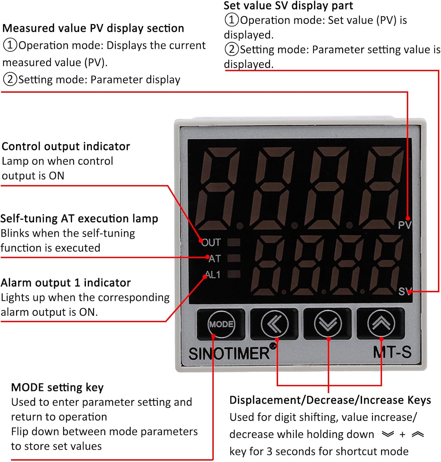
Image: Front panel of the PID temperature controller, detailing the PV (Measured Value) and SV (Setting Value) displays, control indicators (OUT, AT, AL1), and function keys (MODE, Shift, Down, Up).
Section d'affichage
- PV (Measured Value) Display: Affiche la température mesurée actuelle.
- SV (Setting Value) Display: Shows the set temperature or parameter setting value.
- Indicateur de sortie : Lights up when the control output is ON.
- Indicateur AT : Blinks when the self-tuning (Auto-Tune) function is active.
- Indicateur AL1 : Lights up when the corresponding alarm output is ON.
Touches de contrôle
- Touche MODE : Used to enter parameter settings and return to operation. Press to flip down between mode parameters and store set values.
- Touche Maj (<) : Utilisé pour le décalage des chiffres lors du réglage des valeurs.
- Decrease Key (v): Decreases the setting value. Holding for 3 seconds may activate a shortcut mode.
- Increase Key (^): Increases the setting value. Holding for 3 seconds may activate a shortcut mode.
Réglage de la température
- In normal operation mode, the SV display shows the set temperature.
- Utilisez le Decrease (v) et Increase (^) touches permettant de régler la température souhaitée.
- Le Décalage (<) key can be used to move the cursor to adjust specific digits.
- The controller will automatically save the new set value after a short period of inactivity or by pressing the MODE clé.
Parameter Settings and Auto-Tune
To access advanced parameters or initiate the auto-tune function, refer to the detailed programming guide (usually provided separately or accessible via specific key combinations). The AT indicator will blink during auto-tuning.
The controller supports both Celsius (℃) and Fahrenheit (℉) display. This setting can typically be changed within the parameter menu.
Entretien
The SINOTIMER PID Temperature Controller Kit is designed for reliable operation with minimal maintenance. Follow these guidelines to ensure longevity:
- Nettoyage: Nettoyez l'écran et les boutons de la manette avec un chiffon doux et sec. Évitez les nettoyants abrasifs et les solvants.
- Environnement: Ensure the operating environment is within the specified temperature and humidity ranges. Avoid excessive dust, moisture, and corrosive gases.
- Relations: Periodically check all wiring connections for tightness and signs of wear or corrosion. Ensure the heat sink for the SSR is free from obstructions and dust to maintain efficient cooling.
- Thermocouple: Inspect the thermocouple for physical damage or signs of degradation. Replace if necessary to maintain accurate temperature readings.
Dépannage
If you encounter issues with your PID Temperature Controller Kit, refer to the following common problems and solutions:
| Problème | Cause possible | Solution |
|---|---|---|
| Le contrôleur ne s'allume pas. | Absence d'alimentation ou câblage incorrect. | Check power connections (terminals 1 & 2). Ensure AC 100-240V is supplied. |
| Temperature reading is inaccurate or "HHHH" / "LLLL" displayed. | Thermocouple disconnected, reversed polarity, or faulty. | Verify thermocouple connection (terminals 11 & 12) and polarity. Replace thermocouple if damaged. |
| Heater does not turn on/off. | SSR wiring incorrect, SSR faulty, or controller output issue. | Check SSR input wiring from controller (terminals 3 & 9). Verify SSR load wiring (terminals 1 & 2). Test SSR functionality if possible. Ensure controller output (OUT indicator) is active. |
| Controller not maintaining set temperature. | Incorrect PID parameters or insufficient heating/cooling capacity. | Perform auto-tune (AT function) to optimize PID parameters. Ensure the heating element is adequately sized for the application. |
Si le problème persiste après avoir essayé ces solutions, veuillez contacter le service client.
Caractéristiques
- Modèle: SINOTIMER MT-S (PID Temperature Controller)
- Alimentation: 100-240 V CA, 50/60 Hz
- Types d'entrée : K, E, J Thermocouple (K-type screw thermocouple included)
- Plage de température : 0-999℃ / ℉ (Display)
- Sortie de contrôle: Relay / SSR (25DA SSR included)
- Sortie d'alarme: 1 Alarm Relay Output (AC220V/DC30V 3A Resistive load) NO/NC
- Dimensions du contrôleur : 48mm x 48mm (Front Panel), 75mm (Depth)
- SSR Model: FOTEK SSR-25 DA
- Volume d'entrée SSRtage: 3-32 VCC
- Volume de charge SSRtage: 24-380 VCA
- Type de thermocouple : K-Type Screw, 2M length
- Matériel: Flame Retardant ABC material
- Poids de l'article : Approximately 12.7 ounces (total kit)
- Dimensions du colis : 5.28 x 4.21 x 3.11 pouces
Garantie et assistance
For warranty information and technical support, please refer to the documentation provided with your purchase or contact SINOTIMER customer service directly. Keep your purchase receipt for warranty claims.
Manufacturer: SINOTIMER


