1. Introduction
Welcome to the user manual for the Autonics TC4S series temperature controllers, models TC4S-24R and TC4S-14R. These devices are designed for precise temperature regulation in various industrial and commercial applications. This manual provides essential information for safe and efficient operation, including installation, setup, operation, maintenance, and troubleshooting. Please read this manual thoroughly before operating the device and keep it for future reference.
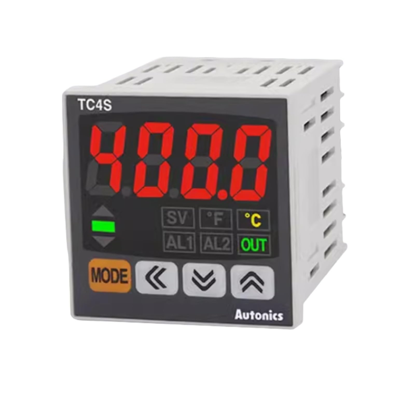
Figure 1 : Face avant view of the Autonics TC4S Temperature Controller. This image shows the display, control buttons, and indicator lights on the front panel of the device.
2. Précautions de sécurité
To ensure safe operation and prevent product damage, observe the following safety precautions:
- Coupez toujours l'alimentation électrique avant d'effectuer tout câblage ou opération de maintenance.
- Assurez-vous d’une mise à la terre appropriée pour éviter les chocs électriques.
- Ne pas démonter ni modifier l'appareil. Confier toute réparation à un personnel qualifié.
- Install the unit in an environment free from excessive vibration, dust, moisture, and corrosive gases.
- Utilisez le volume d'alimentation spécifiétage. Volume incorrecttagCela peut causer des dommages.
- Ensure all wiring connections are secure and correct according to the wiring diagrams.
3. Produit terminéview
The Autonics TC4S series temperature controllers feature a compact design and precise control capabilities. Key components include:
- Afficher: Shows current temperature (PV) and set temperature (SV).
- Boutons de contrôle : Used for setting parameters and navigating menus.
- Voyants lumineux : Provide status feedback (e.g., output ON, alarm).
- Bornier : Located at the rear for power, sensor input, and control output connections.
4. Installation et câblage
4.1 Montage
The TC4S series controllers are designed for panel mounting. Ensure adequate space for ventilation and wiring connections. Cut a panel opening of the specified dimensions (refer to specifications for exact cutout size). Insert the controller into the opening and secure it using the provided mounting brackets.
4.2 Câblage
Connect the power supply, temperature sensor, and control output devices to the terminal block at the rear of the controller. Refer to the wiring diagram typically found on the side of the unit or in the full product datasheet for specific terminal assignments. Ensure all connections are tight and correct to prevent malfunction or damage.
- Alimentation: Connect to the designated power terminals (e.g., 100-240VAC).
- Entrée capteur: Connect your temperature sensor (e.g., thermocouple, RTD) to the sensor input terminals. Observe polarity for thermocouples.
- Sortie de contrôle: Connect your heating/cooling element or relay to the control output terminals. Model TC4S-24R typically features a relay output, while TC4S-14R may have a different output type.
5. Configuration initiale
5.1 Mise sous tension
After completing all wiring, apply power to the controller. The display will typically show the current process value (PV) and the set value (SV). The unit will perform a self-test upon initial power-up.
5.2 Basic Parameter Settings
Access the parameter settings menu using the designated buttons (e.g., MODE or SET button). Common initial settings include:
- Type d'entrée: Select the type of temperature sensor connected (e.g., K-type thermocouple, Pt100 RTD).
- Unité de température: Choisissez entre Celsius (°C) ou Fahrenheit (°F).
- Mode de contrôle : Select between ON/OFF control or PID control, depending on application requirements.
Refer to the detailed parameter list in the full product manual for advanced settings and their functions.
6. Fonctionnement
6.1 Setting the Target Temperature (Set Point)
To set the desired temperature, press the SET button. The SV display will flash, allowing you to adjust the value using the UP/DOWN arrow buttons. Press SET again to confirm the new set point.
6.2 Comprendre les indicateurs d'affichage
- PV (Valeur du processus) : Displays the current measured temperature.
- SV (Valeur définie) : Affiche la température cible.
- Indicateur de sortie : Illuminates when the control output is active (e.g., heating element is ON).
- Indicateur ALM : S'allume lorsqu'une condition d'alarme est remplie.
Modes de contrôle 6.3
The controller supports different control modes:
- Contrôle MARCHE/ARRÊT : The output turns ON when the PV is below the SV and OFF when it exceeds the SV (or vice versa for cooling). This mode is simple but can lead to temperature cycling.
- Contrôle PID : Proportional-Integral-Derivative control provides more precise and stable temperature regulation by calculating the required output based on the error, integral of the error, and derivative of the error. Auto-tuning functions are often available to automatically calculate optimal PID parameters.
7. Entretien
7.1 Nettoyage
Regularly clean the front panel with a soft, dry cloth. Do not use abrasive cleaners, solvents, or water, as these can damage the display or internal components.
7.2 Inspection
Periodically inspect wiring connections for looseness or signs of damage. Ensure the ventilation openings are not obstructed. Check for any unusual noises or smells during operation.
7.3 Stockage
If storing the unit for an extended period, ensure it is kept in a dry, dust-free environment within the specified storage temperature and humidity ranges.
8. Dépannage
This section addresses common issues you might encounter with your temperature controller.
| Problème | Cause possible | Solution |
|---|---|---|
| Le contrôleur ne s'allume pas | Absence d'alimentation électrique ; câblage incorrect ; fusible grillé. | Check power connections; verify wiring against diagram; replace fuse if necessary. |
| Incorrect temperature reading (PV) | Sensor disconnected or faulty; incorrect sensor input type setting; sensor outside measurement range. | Check sensor wiring and connection; verify sensor type setting in parameters; ensure sensor is suitable for the temperature range. |
| Sortie non activée | Set point not reached; output mode incorrect; faulty output device; alarm condition active. | Adjust set point; check control mode (ON/OFF, PID); test external heating/cooling device; check alarm settings. |
| La température oscille largement | PID parameters not tuned correctly; ON/OFF control with large hysteresis. | Perform auto-tuning for PID parameters; adjust hysteresis for ON/OFF control. |
9. Spécifications
Key technical specifications for the Autonics TC4S series temperature controllers:
- Modèles: TC4S-24R, TC4S-14R
- Méthode de contrôle : Contrôle ON/OFF, contrôle P, PI, PD, PID
- Input Sensor: Thermocouple (K, J, T, E, N, R, S, B, C, G, L, U, P), RTD (Pt100, JPt100) - Specific types may vary by model.
- Type de sortie : Relay output (TC4S-24R), SSR drive output, Current output - Specific type varies by model.
- Alimentation: 100-240VAC 50/60Hz (standard), 24VAC 50/60Hz / 24-48VDC - Volume spécifiquetage varie selon le modèle.
- Méthode d'affichage: 7-segment LED (PV: red, SV: green)
- Précision du contrôle : ±0.5% FS ±1 digit (thermocouple/RTD)
- Matériel: Plastique casing
- Température de fonctionnement : -10°C à 50°C (14°F à 122°F)
- Humidité de fonctionnement : 35 à 85 % HR (sans condensation)
10. Garantie et assistance
This Autonics temperature controller is covered by a standard manufacturer's warranty against defects in materials and workmanship. The warranty period typically begins from the date of purchase. Please retain your proof of purchase for warranty claims.
For technical support, service, or warranty inquiries, please contact your authorized Autonics distributor or the customer support department. Provide the model number (TC4S-24R or TC4S-14R) and a detailed description of the issue when seeking assistance.
For the most up-to-date contact information and detailed warranty terms, please visit the official Autonics website or consult the documentation provided with your purchase.


