1. Introduction
The DALY 40A 8S-24S Smart BMS is an advanced Battery Management System designed for Lithium battery packs, including LiFePO4, Li-ion, and LTO chemistries. This BMS features a 1A active balancer to optimize cell performance and prolong battery life. It integrates Bluetooth, RS485, and CAN communication protocols for comprehensive monitoring and control. This manual provides essential information for the safe and efficient installation, operation, and maintenance of your DALY Smart BMS.
Caractéristiques principales :
- Compatibilité polyvalente : Supports battery strings from 4S-24S (12V-84V) and various lithium battery types (LiFePO4, Li-ion, LTO).
- Équilibrage actif : Equipped with a 1A active balancer to equalize cell charge/discharge states, enhancing battery longevity.
- Surveillance intelligente : Integrated Bluetooth for wireless monitoring of cell voltages, temperatures, and other critical parameters via the 'BalanceBMS' app. Optional WiFi for cloud monitoring and data logging.
- Protection complète : Protects batteries against overcharge, overdischarge, overcurrent, short circuits, and high-temperature shutdown.
- Interfaces de communication multiples : Includes UART, RS485, and CAN for flexible integration and control.
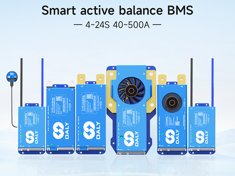
Image: DALY Smart Active Balance BMS highlighting key specifications like battery strings (8-24S), charge/discharge current (40A), balance current (1A), built-in Bluetooth, battery types (Li-ion/LiFePO4/LTO), and communication protocols (UART+RS485+CAN).
2. Consignes de sécurité
Please read and understand all safety instructions before installing or operating the DALY Smart BMS. Failure to follow these instructions may result in electric shock, fire, serious injury, or property damage.
- Always wear appropriate personal protective equipment (PPE), including safety glasses and insulated gloves, when working with batteries and electrical components.
- Ensure the battery pack is disconnected from any power source before beginning installation or maintenance.
- Verify all wiring connections are correct and secure to prevent short circuits. Incorrect wiring can damage the BMS and battery.
- Do not short-circuit any wires, especially during testing. Use insulation tape to secure any unused or excess wires.
- Keep the BMS and battery components away from water, moisture, and flammable materials.
- Do not attempt to disassemble or repair the BMS yourself. Contact qualified personnel for service.
- Ensure proper ventilation around the battery pack and BMS during operation.


Images: Visual representations of the BMS's protection features, including overall protection, pre-charge protection, and misconnection protection.
3. Contenu du colis
Veuillez vérifier que tous les articles listés ci-dessous sont inclus dans votre colis. Si un article est manquant ou endommagé, veuillez contacter le service client.

Image: A visual representation of the DALY BMS package contents, including the Smart Active Balance BMS unit, P-&-B- cable, screws, sampling cable, B+ cable, NTC (temperature sensor), user manual, packaging box, and RS485/CAN port cable.
- Smart Active Balance BMS Unit
- P-&-B- Cable
- Screws (2 Pcs)
- Sampcâble ling
- B+ Cable
- NTC (Temperature Sensor) - One standard, two optional
- Manuel d'utilisation
- Boîte d'emballage
- RS485/CAN Port Cable
4. Guide d'installation
This section provides step-by-step instructions for installing your DALY Smart BMS. Ensure the battery pack is completely disconnected before proceeding.
4.1. Vidéo d'installation
Video: An official installation guide for the DALY Smart Active Balancing BMS, demonstrating the wiring process for an 8S battery pack. This video covers connecting the sampling cables, B- wire, NTC sensor, and B+ wire, along with verification steps.
4.2. Step-by-Step Wiring Instructions (Example: 8S Battery Pack)
- Identifier les bornes de la batterie : Locate the total positive terminal and the total negative terminal of your battery pack.
- Connect B- Wire: Connect the first black cable of the sampling wire harness and the blue B- wire to the total negative terminal of the battery pack. Ensure a secure connection.
- Connecter Sampling Cables: Connect the remaining sampling cables in sequential order to the positive terminals of each cell, starting from B1, B2, B3, and so on, up to the last cell's positive terminal (e.g., B8 for an 8S pack).
Prudence: If using fewer series than the maximum supported by the BMS, do not short-circuit the excess wires. Securely tape them up with insulation tape to prevent accidental contact. - Connectez le fil B+ : Connect the red B+ wire from the sampling harness to the total positive terminal of the battery pack.
- Vérifier Sampling Cable Connections: Before plugging the sampling cable into the BMS, use a multimeter to check the voltage readings. Place the black probe on B0 (the first black wire) and the red probe on B1, then B2, B3, etc. The multimeter should display positive voltage readings that increase step by step. If the readings are correct, the wiring is accurate.
Important: During this testing, do not let the two multimeter probes touch each other, as this may cause a cable short circuit. - Connect BMS B- Terminal: Connect the main blue B- wire from the battery pack to the B- terminal on the BMS unit.
- Insert Temperature Sensor (NTC): Insert the NTC (temperature sensor) into the designated NTC port on the BMS.
- Plug in SampCâble ling : Branchez soigneusement le sampBranchez le faisceau de câbles dans le port correspondant du BMS.
- Connect BMS B+ Wire: Connect the red B+ wire from the sampling harness to the B+ terminal on the BMS.
- Verify BMS Power: If the green light on the BMS illuminates, the BMS is working properly and has been successfully installed.

Image: A DALY BMS unit connected to a battery pack, illustrating the main B- and B+ connections along with the multi-pin sampling cable connected to individual cell terminals.
5. Mode d'emploi
The DALY Smart BMS offers advanced monitoring and control capabilities through its integrated communication interfaces.
5.1. Surveillance via application Bluetooth
Download the 'BalanceBMS' app from your device's app store (available on iOS and Android). Once installed, connect to your BMS via Bluetooth to monitor real-time battery parameters such as:
- Vol de cellule individuelletages
- Volume total de la batterietage
- Courant de charge/décharge
- Température de la batterie
- État de charge (SOC)
- Protection status and alerts
The app also allows for configuration of certain BMS parameters and provides data logging capabilities.
5.2. RS485 and CAN Communication
For advanced integration with other systems (e.g., inverters, motor controllers), the BMS supports RS485 and CAN communication. Refer to the detailed communication protocol documentation (usually provided separately or available from DALY support) for specific implementation guidelines.
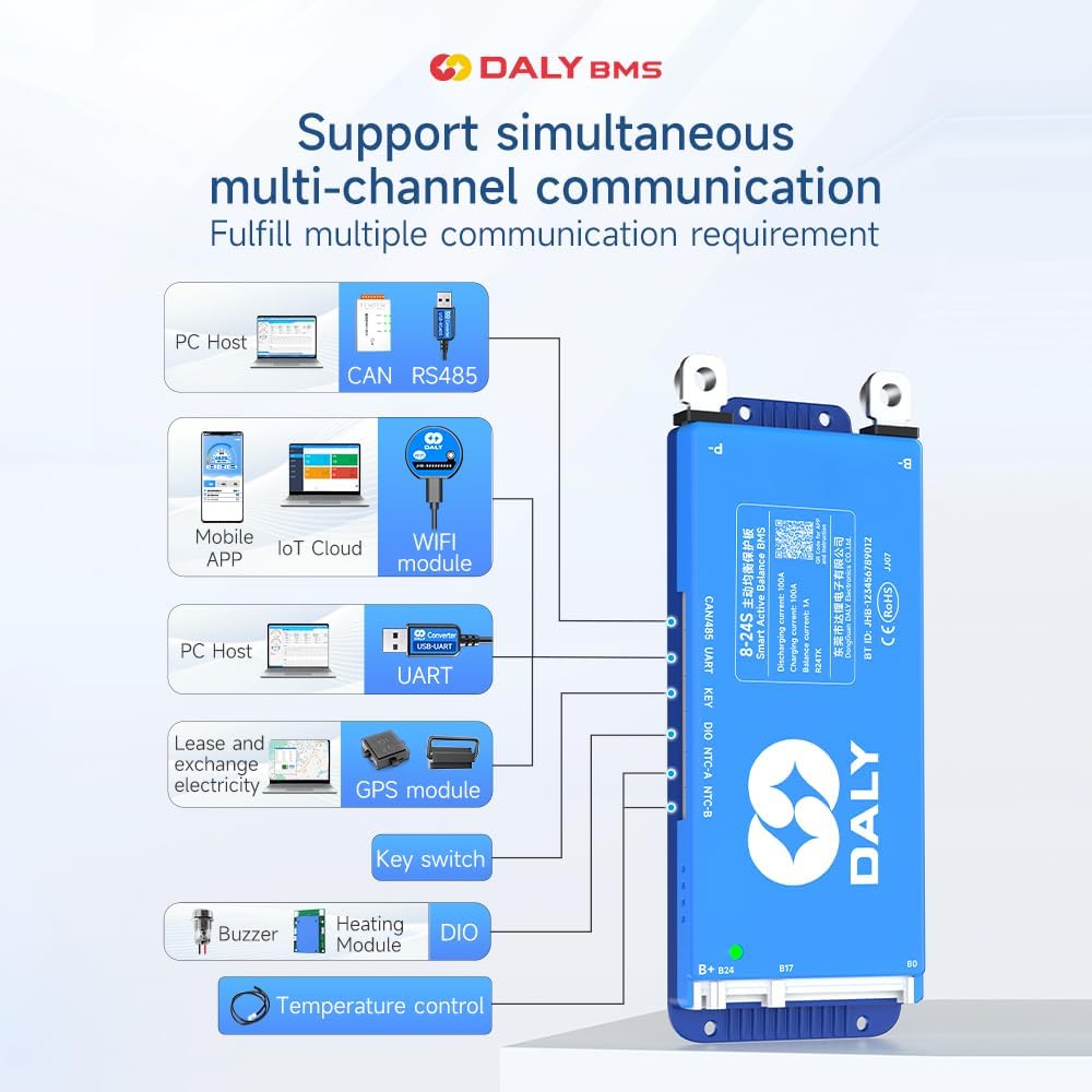
Image: Diagram illustrating the DALY BMS's support for simultaneous multi-channel communication, including PC Host (CAN, RS485, UART), Mobile APP (Bluetooth, IoT Cloud, WiFi module), GPS module, Key switch, Buzzer, Heating Module, and Temperature control.
6. Entretien
Proper maintenance ensures the longevity and optimal performance of your DALY Smart BMS and battery pack.
- Inspection régulière : Vérifiez régulièrement le serrage de tous les branchements électriques et recherchez les signes de corrosion ou de dommages.
- Propreté: Keep the BMS unit clean and free from dust and debris. Use a dry, soft cloth for cleaning.
- Surveillance de la température : Monitor battery and BMS temperatures, especially during charging and discharging, to ensure they remain within safe operating limits.
- Mises à jour du micrologiciel : Check the DALY website or app for any available firmware updates for your BMS model to ensure you have the latest features and bug fixes.
- Stockage: If storing the battery pack for an extended period, ensure it is charged to a recommended storage voltage (typically 50-60% SOC) and stored in a cool, dry place.
7. Dépannage
If you encounter issues with your DALY Smart BMS, refer to the following common troubleshooting steps:
| Problème | Cause possible | Solution |
|---|---|---|
| BMS not powering on (no green light) | Incorrect B- or B+ wiring; sampling cable not fully inserted; battery voltage trop bas. | Check all main power and sampling cable connections. Ensure battery voltage is within the BMS's operating range. Re-insert sampling cable firmly. |
| Vol incorrecttage readings in app | Sampling cables connected in wrong order or loose. | Re-verify sampling cable connections using a multimeter as described in the installation section. Ensure correct sequence. |
| Overcharge/Overdischarge protection triggered | Battery cells reached voltage limites. | Stop charging/discharging. Allow cells to balance. Check charger/load settings. |
| Protection contre les surintensités/courts-circuits déclenchée | Excessive current draw; external short circuit. | Reduce load. Inspect external wiring for short circuits. |
| Problèmes de connexion Bluetooth | BMS not powered; app issues; distance too far. | Ensure BMS is powered. Restart app and phone's Bluetooth. Move closer to the BMS. |
If the problem persists after attempting these solutions, please contact DALY customer support for further assistance.
8. Spécifications
The following are the technical specifications for the DALY 40A 8S-24S Smart BMS (Model: R24TH-40A):
| Fonctionnalité | Détail |
|---|---|
| Numéro de modèle | R24TH-40A |
| Supported Battery Strings | 8S-24S |
| Vol d'entréetaget gamme | 24V-84V (depending on cell configuration) |
| Courant de charge/décharge | 40A |
| Courant de solde actif | 1A |
| Types de batteries pris en charge | NCM (Li-ion), LFP (LiFePO4), LTO |
| Interfaces de communication | Bluetooth, RS485, CAN, UART |
| Dimensions du produit (L x l x H) | 4.92 x 2.6 x 0.62 pouces (125 x 66 x 15.7 mm) |
| Poids de l'article | 6.2 once (177 grammes) |
| Fabricant | Dongguan Daly Electronics Co., Ltd |

Image: Table showing applicable current ratings and physical dimensions for various DALY BMS models, including 100A, 150A/200A, and 250-500A versions. Note: The current model is 40A, but this image provides a general overview of the product line's physical characteristics.
9. Garantie et assistance
DALY provides an 18-month warranty for this Smart BMS. This warranty covers defects in materials and workmanship under normal use.
9.1. Couverture de la garantie
The warranty period begins from the date of purchase. Please retain your proof of purchase for warranty claims. The warranty does not cover damage caused by:
- Improper installation or wiring
- Mauvaise utilisation, abus ou négligence
- Modifications ou réparations non autorisées
- Operating outside specified environmental conditions
- Accidental damage or natural disasters
9.2. Assistance clientèle
For technical assistance, warranty claims, or any questions regarding your DALY Smart BMS, please contact our friendly customer service. Refer to the contact information provided with your product packaging or visit the official DALY website.


