1. Introduction
The Waveshare Industrial 8-Channel Analog Acquisition Module (Model WA8TAI-8CH) is a high-precision device designed for industrial data acquisition. It supports 8 channels of 12-bit analog input, capable of acquiring both voltage (0-10V) and current (0-20mA or 4-20mA) signals. This module utilizes the Modbus RTU protocol over an RS485 interface, making it suitable for integration into various industrial control systems. Key features include a wide DC 7-36V power supply range, multiple isolation protections, and a robust rail-mount design for easy installation.

Figure 1.1: Waveshare Industrial 8-Channel Analog Acquisition Modules.
2. Contenu du colis
Vérifiez que tous les éléments énumérés ci-dessous sont inclus dans votre colis :
- Modbus RTU Analog Input 8CH (B) Module x1
- Power Supply Terminal Adapter x1
- Jumper Cap (10 PCS) x1

Figure 2.1 : Contenu de l'emballage.
3. Caractéristiques
The WA8TAI-8CH module incorporates several features designed for reliable and accurate industrial data acquisition:
- 8-Channel 12-Bit High-Precision Acquisition: Supports simultaneous acquisition of 8 analog signals with 12-bit resolution, offering high accuracy.
- Voltage and Current Input: Capable of acquiring both voltage (0-10V) and current (0-20mA or 4-20mA) signals, configurable via jumpers.
- Modbus RTU Protocol: Communicates using the standard Modbus RTU protocol over RS485, allowing for configurable device addresses (1-255).
- Vol largetage Alimentation : Operates with a DC 7-36V power input, providing flexibility for various industrial power sources.
- Multiple Isolation Protections: Features onboard unibody power supply isolation, magnetic isolation, resettable fuse, and Transient Voltage Suppressor (TVS) for enhanced reliability and anti-interference in industrial environments.
- Composants de haute qualité : Utilizes high-precision resistors and zero-drift operational amplifiers for accurate data acquisition.
- Fonctionnement stable : Includes a built-in oversampling digital filtering algorithm and an onboard watchdog to ensure stable output without system crashes.
- Rail-Mount Design: Designed for easy installation on a 35mm standard DIN rail, supporting stacking for multiple modules.
- Indicateurs de statut: Three LEDs (RXD, TXD, STATUS) provide visual feedback on MCU status and signal transmission.

Figure 3.1: Features at a Glance.

Figure 3.2: Industrial Grade Isolated Protection.
4. Spécifications
| Paramètre | Valeur |
|---|---|
| Modèle | Entrée analogique Modbus RTU 8 canaux (B) |
| Interface de communication | RS485 |
| Débit en bauds | 4800, 9600, 19200, 38400, 57600, 115200, 128000, 256000 |
| Format de communication par défaut | 9600 8, N, 1, XNUMX |
| Protocole Modbus | Protocole Modbus RTU standard |
| Alimentation électrique | DC 7-36V |
| Sampling Précision | 12-bit resolution, accuracy <3% |
| Taux de mise à jour des données | 25 Hz |
| Mode d'entrée | Supports single-ended/differential input, voltage et acquisition simultanée actuelle |
| Mode par défaut | 8-ch voltage mode, 0-10V |
| Gamme | 0-10V / 2-10V, 0-20mA / 4-20mA |
| Courant Samprésistance de courant | 499 Ω |
| Dimensions (L x l x H) | 121.0 x 72.0 x 35.0 mm (environ) |
| Poids | 5.9 onces (environ) |

Figure 4.1: Module Specifications.
5. Interface terminéeview
The module features clearly labeled terminals and LED indicators for easy connection and status monitoring.
5.1. Terminal Definitions
- 7~36V : DC power input (positive).
- GND : Terre d'alimentation.
- AI1+ to AI8+: Positive terminals for analog input channels 1 to 8.
- AI1- to AI8-: Negative terminals for analog input channels 1 to 8.
- A+ : RS485 differential signal positive terminal.
- B- : RS485 differential signal negative terminal.
5.2. Indicateurs LED
- RXD : Receive Data indicator. Flashes when data is being received via RS485.
- TXD : Transmit Data indicator. Flashes when data is being transmitted via RS485.
- STATUT: Working Status indicator. Indicates the module's operational state.

Figure 5.1: Module Front View with Terminals and Indicators.

Figure 5.2: Interface Introduction and Indicators.
6. Installation et configuration
6.1. Connexion de l'alimentation
Connect a DC power source within the 7-36V range to the '7~36V' and 'GND' terminals. Ensure correct polarity to prevent damage to the module. The module features anti-reverse protection.
6.2. RS485 Communication Connection
Connect the RS485 A+ terminal of the module to the A+ terminal of your RS485 master device (e.g., PC, PLC) and the B- terminal of the module to the B- terminal of your master device. Ensure proper wiring for half-duplex communication.

Figure 6.1: Power Supply and RS485 Interface.
6.3. Analog Input Mode Selection
The module supports both voltage and current acquisition. The specific input range (e.g., 0-10V, 0-20mA, 4-20mA) is configurable via internal jumpers. Refer to the manufacturer's wiki or detailed product documentation for precise jumper settings for each channel. Incorrect jumper settings may lead to inaccurate readings or module damage.
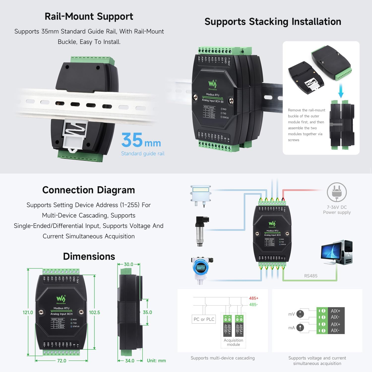
Figure 6.2 : Volumetage/Current Acquisition Range Configuration.
6.4. Analog Input Connection
Connect your analog sensors to the AIx+ and AIx- terminals for each channel. For voltage inputs, connect the sensor's positive output to AIx+ and negative/ground to AIx-. For current inputs, connect the sensor in series with the AIx+ and AIx- terminals, ensuring the current flows correctly through the module's internal samprésistance de ling.
6.5. Modbus RTU Configuration
The module's device address (1-255), baud rate, and parity settings are configured via Modbus commands from the master device. The default communication format is 9600, N, 8, 1. Consult the Waveshare product wiki for detailed Modbus register maps and command exampfichiers pour la configuration.
7. Utilisation du module
Once powered and configured, the module operates as a Modbus RTU slave device. The master device sends Modbus commands to read the analog input values from the module's registers. The module provides 12-bit digital values corresponding to the analog input signals.
7.1. Vol.tage Acquisition (0-10V)
En voltage mode, the module measures input voltages from 0V to 10V. The 12-bit resolution provides 4096 discrete levels across this range. The acquired digital value can be scaled by the master device to represent the actual voltage.
7.2. Current Acquisition (0-20mA / 4-20mA)
In current mode, the module measures input currents from 0mA to 20mA or 4mA to 20mA, depending on the jumper configuration. Similar to voltage mode, the 12-bit digital output needs to be scaled by the master device to obtain the actual current value.

Figure 7.1: Module Version Options and Supported Ranges.
8. Schémas de connexion
Below are typical connection diagrams for integrating the module into an industrial system.

Figure 8.1: Typical Connection Diagram for Sensors and Modbus Network.
9. Rail-Mount and Stacking Installation
The module is designed for easy installation on a standard 35mm DIN rail. It also supports stacking multiple modules together to create a compact and organized system.
9.1. Rail-Mount Support
Attach the module to a 35mm standard guide rail using its integrated rail-mount buckle. Ensure it clicks securely into place.
9.2. Installation d'empilage
For stacking, remove the rail-mount buckle from the outer module. Then, align and assemble the two modules together using screws to secure them.

Figure 9.1: Rail-Mount and Stacking Installation.
10. Dépannage
If you encounter issues with your module, refer to the following common troubleshooting steps:
- Pas d'alimentation : Vérifiez que l'alimentation CC 7-36 V est correctement connectée et fournit la tension spécifiée.tage. Check the power supply terminal adapter and wiring for any loose connections or damage.
- No RS485 Communication:
- Ensure RS485 A+ and B- terminals are correctly wired to the master device.
- Check that the module's device address is unique on the bus and matches the address used by the master.
- Verify that the baud rate, parity, data bits, and stop bits are consistent between the module and the master device.
- Observe the RXD and TXD LEDs; they should flash during communication. If not, check wiring and master device configuration.
- For long RS485 bus lines, ensure proper termination resistors (120 Ohm) are used at both ends of the bus.
- Inaccurate Analog Readings:
- Confirm that the internal jumpers for voltage/current input mode and range are set correctly for your sensor type.
- Check the sensor's output and wiring for any faults or interference.
- Ensure the sensor is powered correctly and operating within its specified range.
- While the module offers high precision, external calibration of the sensor or scaling in the master device may be required for critical applications.
- Module Malfunction After Power Disconnection: Ensure that power connections are stable and secure. Avoid abrupt disconnections, especially under load, as this can potentially stress components.
11. Entretien
To ensure the longevity and optimal performance of your Waveshare Industrial 8-Channel Analog Acquisition Module, follow these maintenance guidelines:
- Nettoyage: Keep the module clean and free from dust and debris. Use a soft, dry cloth for cleaning. Avoid using liquid cleaners or solvents.
- Environnement: Operate the module within its specified environmental conditions (temperature, humidity). Avoid exposure to extreme temperatures, direct sunlight, or corrosive environments.
- Relations: Vérifiez régulièrement tous les branchements électriques pour vous assurer qu'ils sont bien fixés et exempts de corrosion.
- Ventilation: Ensure adequate airflow around the module, especially if multiple modules are stacked, to prevent overheating.
12. Garantie et assistance
For warranty information, technical support, or service inquiries, please contact your Waveshare product reseller or visit the official Waveshare website. Keep your purchase receipt or proof of purchase for warranty claims.


