1. Introduction
This manual provides comprehensive instructions for the safe and effective operation, maintenance, and troubleshooting of the RS PRO RSDS 1052 DL+ Digital Storage Oscilloscope. Please read this manual thoroughly before using the device to ensure proper functionality and to prevent damage or injury.
The RS PRO RSDS 1052 DL+ is a versatile 2-channel digital storage oscilloscope with a 50 MHz bandwidth, designed for precise signal analysis. It features a 7-inch TFT LCD display for clear waveform visualization and supports various measurement parameters and mathematical operations.
2. Consignes de sécurité
Always adhere to the following safety precautions to prevent electric shock, fire, or damage to the instrument.
- Source d'alimentation : Ensure the oscilloscope is connected to a power source within the specified voltage range (100-240V AC, 50/60Hz).
- Mise à la terre : The instrument must be properly grounded to prevent electric shock. Do not defeat the grounding plug.
- Environnement: Operate the oscilloscope in a dry, well-ventilated area, away from direct sunlight, high temperatures, and excessive dust.
- Sondes: Use only probes supplied or recommended by RS PRO. Ensure probes are correctly rated for the voltage étant mesuré.
- Entretien: Refer all servicing to qualified service personnel. Do not attempt to open the instrument casing unless explicitly instructed.
- Catégorie de sécurité : This device is rated CAT I, CAT II. Observe all safety warnings on the device and in this manual.
3. Produit terminéview et composants
Cette section fournit un aperçuview of the RS PRO RSDS 1052 DL+ oscilloscope and its main components.
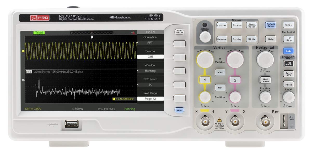
Figure 3.1 : Face avant View of the Oscilloscope. This image shows the front panel of the RS PRO RSDS 1052 DL+ oscilloscope, highlighting the 7-inch TFT LCD display, control knobs, function buttons, and input connectors for channels 1 and 2. The screen displays a typical waveform and FFT analysis.

Figure 3.2 : Angulaire View of the Oscilloscope. This image provides an angled perspective of the RS PRO RSDS 1052 DL+ oscilloscope, showcasing its compact design and integrated handle for portability. The side ventilation grilles are also visible.

Figure 3.3 : Arrière View of the Oscilloscope. This image displays the rear panel of the RS PRO RSDS 1052 DL+ oscilloscope, featuring the power input, USB device port, USB host port, LAN port, and Pass/Fail output. Safety warnings and product labels are also visible.
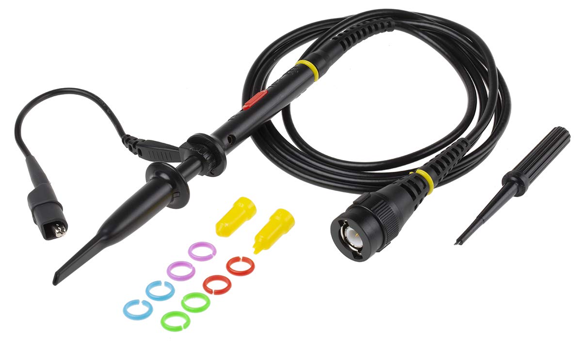
Figure 3.4: Oscilloscope Probe and Accessories. This image shows a passive oscilloscope probe (1:1/10:1) along with various accessories, including colored rings for channel identification and probe tip covers. These are essential for connecting signals to the oscilloscope.

Figure 3.5: Power Plugs and Probe Tip. This image displays an assortment of power plugs (EU, UK, US types) that may be included with the oscilloscope, along with a specialized probe tip. These ensure compatibility with various power outlets and provide versatility for measurements.
3.1 Accessoires inclus
The RS PRO RSDS 1052 DL+ typically includes the following accessories:
- Passive Probe 1:1/10:1 (x2)
- Câble USB
- Guide de démarrage rapide
- Certificat de qualité
- Cordon d'alimentation (spécifique à la région)
- CD (including User Manual and EasyScopeX software)
4. Installation
4.1 Déballage et inspection
- Carefully remove the oscilloscope and all accessories from the packaging.
- Inspect the instrument for any signs of physical damage during transit. If damage is found, contact your supplier immediately.
- Verify that all included accessories listed in Section 3.1 are present.
4.2 Connexion d'alimentation
- Assurez-vous que l'interrupteur d'alimentation situé sur le panneau arrière est en position OFF.
- Connect the provided power cord to the AC input on the rear panel of the oscilloscope.
- Plug the other end of the power cord into a grounded AC power outlet. The oscilloscope supports 100-240V AC, 50/60Hz.
4.3 Connexion et compensation de la sonde
- Connect the BNC connector of the passive probe to one of the input channels (CH1 or CH2) on the front panel.
- Attach the probe tip to the probe compensation output (usually a square wave test signal) on the front panel.
- Adjust the compensation trimmer on the probe until the displayed square wave is flat-topped, without overshoot or undershoot. This ensures accurate measurements.
5. Mode d'emploi
5.1 Fonctionnement de base
- Marche/Arrêt : Press the power button on the front panel to turn the oscilloscope on or off.
- Configuration automatique : Appuyez sur le Auto bouton permettant d'ajuster automatiquement les paramètres verticaux, horizontaux et de déclenchement pour un affichage stable de la forme d'onde.
- Commandes verticales : Utilisez le VOLT/DIV knob to adjust the vertical scale (voltage per division) and the POSITION knob to move the waveform vertically.
- Commandes horizontales : Utilisez le SEC/DIV knob to adjust the horizontal scale (time per division) and the POSITION knob to move the waveform horizontally.
- Commandes de déclenchement : Ajustez le NIVEAU knob to set the trigger threshold. The trigger ensures a stable display of repetitive waveforms.
5.2 fonctions avancées
- Fonctions de mesure : Appuyez sur le Mesure button to access automatic measurement parameters such as Vpp, Vmax, Vmin, Freq, Period, etc.
- Fonctions mathématiques : Appuyez sur le Mathématiques button to perform mathematical operations on waveforms (e.g., Add, Subtract, Multiply, Divide, FFT).
- Stockage et rappel : Utilisez le Enregistrer/Rappeler buttons to save waveform data, setups, or screenshots to internal memory or a USB drive.
- Connectivité USB : Connect a USB drive to the front panel USB host port for data storage. Use the rear USB device port to connect the oscilloscope to a PC for data transfer and control via EasyScopeX software.
6. Entretien
6.1 Nettoyage
- Débranchez le cordon d’alimentation avant le nettoyage.
- Utilisez un chiffon doux et sec.amp cloth with mild detergent to clean the exterior of the instrument.
- Do not use abrasive cleaners or solvents that may damage the plastic parts.
- Veillez à ce qu'aucun liquide ne pénètre dans l'instrument.
6.2 Étalonnage
The oscilloscope is factory calibrated. For optimal performance, periodic calibration by qualified personnel is recommended, typically every 12-24 months, depending on usage and environmental conditions.
6.3 Stockage
When not in use for extended periods, store the oscilloscope in a dry, dust-free environment, away from extreme temperatures and humidity.
7. Dépannage
Cette section propose des solutions aux problèmes courants que vous pourriez rencontrer.
| Problème | Cause possible | Solution |
|---|---|---|
| Pas de courant | Cordon d'alimentation débranché ; interrupteur sur la position « arrêt » ; fusible grillé | Check power cord connection; Turn power switch on; Contact service for fuse replacement. |
| Aucune forme d'onde affichée | Input signal too small/large; Incorrect vertical/horizontal settings; Trigger not set correctly; Probe not connected | Adjust VOLTS/DIV and SEC/DIV; Use Auto Setup; Adjust trigger level; Ensure probe is connected and compensated. |
| Forme d'onde instable | Incorrect trigger settings; No trigger source selected | Adjust trigger level and mode; Select appropriate trigger source (e.g., CH1, CH2, Ext). |
| Forme d'onde déformée | Probe compensation incorrect; Probe damaged; Input overloaded | Perform probe compensation; Try a different probe; Check input signal amplatitude. |
If the problem persists after attempting these solutions, please contact RS PRO customer support.
8. Spécifications
Key technical specifications for the RS PRO RSDS 1052 DL+ Digital Storage Oscilloscope:
- Canaux analogiques : 2
- Oscilloscope Type: Stockage numérique
- Bande passante : 50 MHz
- S en temps réelample taux : Up to 500 MSa/s
- Profondeur de la mémoire : 32 Kpts
- Type d'affichage : Écran LCD TFT
- Taille de l'écran : 7 pouces (800 x 480 pixels)
- Sensibilité verticale : 2mV/div to 10V/div
- Plage de base de temps : 10ns/div à 50s/div
- Alimentation: Mains operated (100-240V AC, 50/60Hz)
- Poids: 2.5 kg
- Catégorie de sécurité : CAT I, CAT II
- Interfaces : RS232, USB Host, USB Device, LAN
9. Garantie et assistance
RS PRO products are manufactured to high standards and are typically covered by a manufacturer's warranty. Please refer to the warranty card included with your product or visit the official RS PRO webConsultez le site pour connaître les conditions générales de garantie détaillées.
For technical support, service, or inquiries regarding your RS PRO RSDS 1052 DL+ oscilloscope, please contact RS PRO customer service through their official channels. Contact information can usually be found on the RS PRO websur le site ou dans la documentation fournie avec le produit.
RS PRO Official Website: https://uk.rs-online.com/web/


