1. Introduction
The E90-DTU(433L37) is a robust wireless data transceiver designed for reliable long-distance communication. It integrates digital data processing, modulation, demodulation, and error correction functionalities. Unlike analog FM transceivers, it offers a transparent RS232/RS485 interface for seamless integration with various devices. Operating in the 433MHz frequency band, this module incorporates advanced ultra-narrow band modulation technology, along with built-in power ampAmplificateurs (PA) et faible bruit amplifiers (LNA), to achieve a maximum transmitting power of 5W and significantly improved receiving sensitivity. This design ensures enhanced communication stability and a remarkable communication distance of up to 20km, making it ideal for applications requiring real-time and reliable data transmission in diverse and complex geographical environments.
2. Principales caractéristiques
- Advanced LoRa Modulation: Utilizes military-grade LoRa spread spectrum technology for significantly enhanced communication distance and stability.
- Puissance de sortie élevée : Transmission power up to 5W, with multi-level adjustable settings, meeting European industrial standards.
- Wide Interface Support: Provides transparent RS232 and RS485 interfaces for versatile connectivity.
- Conception robuste : Features an all-aluminum alloy shell for compact size, easy installation, good heat dissipation, and strong anti-interference ability.
- Protection complète : Includes power reverse connection protection, over-connection protection, and antenna surge protection.
- Configuration flexible : Powerful software functions allow all parameters (power, frequency, air speed, address ID, etc.) to be set through programming.
- Faible consommation d'énergie : Standby current is only 50mA (even lower in power saving and sleep modes), with an emission current of 1.2A.
- Haute fiabilité : Built-in watchdog and accurate time layout ensure automatic module restart and continued operation with previous settings in case of exceptions.
- Compensation de température : Temperature compensators ensure frequency stability better than ±1.5PPM.
- Modbus Adaptation: Supports large single packages up to 197 bytes and Modbus adaptation.
- Alimentation flexible : Simple and efficient power supply design, supporting 10~28V power supply from various devices or line pressure modes.
3. Produit terminéview
3.1. Apparence de l'appareil

Figure 3.1 : Face avant view of the E90-DTU(433L37) Wireless Transceiver, showing RS232, RS485, power input, and antenna connector.
3.2. Dimensions

Figure 3.2: Dimensions of the E90-DTU(433L37) module, approximately 102mm by 79mm.
3.3. Composants matériels

Figure 3.3 : Détaillé view of hardware components including Antenna Interface, Dip Switch (M0, M1), Power Interface (DC-IN), Function Indicators (PWR, TXD, RXD), RS485 terminals (485_A, 485_B, GND, VCC), and RS232 port.
4. Basic Functionality and Connectivity
The E90-DTU(433L37) acts as a wireless data transceiver, enabling communication between devices without the need for physical serial cables. It supports both RS232 and RS485 interfaces, providing a flexible solution for various data transmission needs.
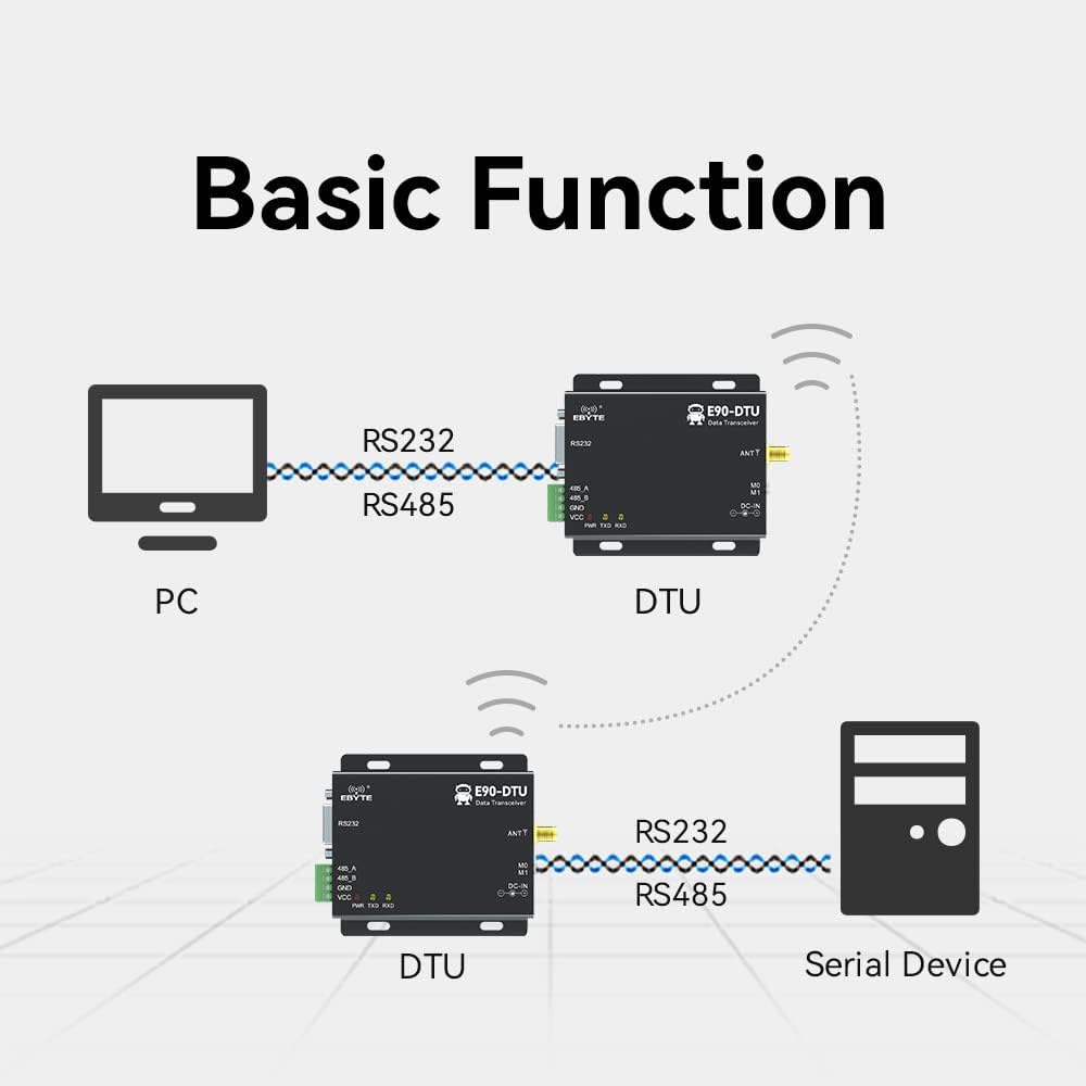
Figure 4.1: Diagram illustrating the basic function of the E90-DTU, showing wireless data transmission between a PC and a serial device via two DTU modules.
This module facilitates wireless data transmission and reception, effectively replacing traditional serial cable connections. It can connect to a PC or other serial devices via its RS232 or RS485 ports, allowing for seamless data exchange over a wireless link.
5. Configuration et installation
5.1. Connexion électrique
Connect the power supply to the DC-IN port. The module supports a wide input voltage range of 10V to 28V. Ensure correct polarity (+ and -) as indicated on the device to prevent damage.
5.2. Connexion de l'antenne
Attach the appropriate 433MHz antenna to the ANT connector. Ensure the antenna is securely fastened to guarantee optimal signal transmission and reception performance.
5.3. Serial Interface Connection
- RS232: Connect your RS232 compatible device (e.g., PC, PLC) to the DB9 serial port on the E90-DTU.
- RS485: Connect your RS485 compatible device to the 485_A and 485_B terminals. Pay close attention to proper A/B wiring for correct differential signaling.
5.4. Configuration du commutateur DIP
The module features M0 and M1 dip switches, which are used to configure various operating modes. These modes determine how the module functions (e.g., transparent transmission, configuration mode). Refer to the detailed technical manual for specific mode configurations and their corresponding dip switch settings.
6. Mode d'emploi
6.1. Mise sous tension
Once all necessary connections (power, antenna, serial interface) are securely established, apply power to the E90-DTU module. The PWR indicator LED will illuminate, indicating that the device is powered on.
6.2. Transmission de données
In transparent transmission mode, data sent to the RS232 or RS485 port of one E90-DTU module will be wirelessly transmitted and subsequently output from the corresponding serial port of the paired module. The TXD (transmit) and RXD (receive) indicator LEDs will flash during active data transmission and reception, respectively, providing visual feedback on communication status.
6.3. Logiciel de configuration
The E90-DTU supports configuration and management via dedicated software, which is typically available for download from the manufacturer's official website. This software provides a user-friendly interface to set various operational parameters such as power output, operating frequency, air speed, and address ID. The device status can also be conveniently monitored through the indicator lights.

Figure 6.1: Screenshot of the Function Configuration Software, available for download from the official website, used to manage module parameters.
For advanced networking, the module also supports Modbus TCP to RTU conversion and various gateway modes, including active upload mode, multi-host gateway mode, stored gateway mode, and configurable gateway mode, offering flexibility for complex system integrations.
Vidéo 6.1 : Un overview video demonstrating the E90-DTU(433L37) Wireless Transceiver, including unboxing, physical features, and basic connectivity concepts. This video highlights the device's interfaces and general appearance.
7. Applications
The E90-DTU(433L37) is a versatile wireless data transceiver suitable for a wide range of applications that require reliable and long-distance wireless data transmission:

Figure 7.1: Visual representation of various applications for the E90-DTU, including Smart Home, Agricultural Applications, Intelligent Warehouse, Industrial Applications, Device Management, and Wireless Data collection.
- Maison intelligente: Ideal for wireless control and data exchange within home automation systems, enabling seamless communication between smart devices.
- Applications agricoles : Used for monitoring and control of agricultural equipment and sensors over extensive areas, such as tracking soil moisture, weather conditions, or irrigation systems.
- Intelligent Warehouse: Facilitates data collection from sensors and devices within large warehouse environments, optimizing inventory management and logistics.
- Applications industrielles : Provides reliable data transmission for Programmable Logic Controllers (PLCs), Remote Terminal Units (RTUs), and other industrial control systems, crucial for automation and process control.
- Gestion des appareils : Enables centralized management and monitoring of distributed devices, simplifying oversight and maintenance across various locations.
- Wireless Data: Serves as a general-purpose wireless data link in scenarios where wired connections are impractical or costly, offering flexibility and ease of deployment.
8. Entretien
To ensure the longevity and optimal performance of your E90-DTU(433L37) Wireless Transceiver, follow these maintenance guidelines:
- Propreté: Veillez à ce que l'appareil reste propre et exempt de poussière et de débris. Utilisez un chiffon doux et sec pour le nettoyer.
- Ventilation: Ensure proper ventilation around the device to prevent overheating, especially during continuous operation.
- Conditions environnementales : Avoid exposing the device to extreme temperatures, high humidity, direct sunlight, or corrosive environments.
- Intégrité de la connexion : Regularly inspect all cable connections (power, serial, antenna) to ensure they are secure and free from damage.
- Entretien: Do not attempt to open, disassemble, or repair the device yourself. Refer all servicing to qualified technical personnel to avoid voiding the warranty or causing further damage.
9. Dépannage
This section provides solutions to common issues you might encounter with the E90-DTU(433L37) Wireless Transceiver.
| Problème | Cause possible | Solution |
|---|---|---|
| Pas d'alimentation (LED d'alimentation éteinte) | Vol d'alimentation incorrecttage or polarity; loose power connection; faulty power adapter. | Vérifiez le volume de l'alimentationtage is within the 10-28V range. Check power cable connections for secure fit and correct polarity. Test with a known good power adapter. |
| No Data Transmission/Reception | Incorrect serial port settings (baud rate, parity, data bits, stop bits); antenna not connected or faulty; modules not paired or out of range; incorrect M0/M1 dip switch settings; interference. | Ensure serial port settings on connected devices match the module's configuration. Confirm antenna is securely connected and undamaged. Verify modules are within operational range and configured correctly (M0/M1 switches for operating mode). Check for sources of RF interference. |
| Intermittent Connection or Poor Range | Environmental interference; weak signal due to obstacles; loose antenna connection; antenna not optimized for frequency. | Relocate modules to minimize interference. Ensure clear line of sight between modules if possible. Check antenna connection and ensure it is appropriate for the 433MHz band. Consider using higher gain antennas or external antennas if needed. |
| Module Not Responding to Configuration Software | Incorrect serial port selected in software; module not in configuration mode; driver issues. | Ensure the correct COM port is selected in the software. Check M0/M1 dip switch settings to ensure the module is in configuration mode (if applicable for your software version). Install or update necessary USB-to-serial drivers. |
10. Spécifications
- Modèle: E90-DTU(433L37)
- Gamme de fréquences : 410 à 441 MHz
- Puissance de transmission : 37 dBm (5 W)
- Distance de communication : Up to 20km (line of sight, ideal conditions)
- Interface: RS232 (DB9), RS485 (terminal block)
- Technologie de modulation : LoRa Spread Spectrum
- Vol. d'alimentationtage: 10V ~ 28V CC
- Courant de veille : Environ 50 mA
- Courant d'émission : Approximately 1.2A
- Stabilité de fréquence : Better than ±1.5PPM (with temperature compensation)
- Débit de données : 1.2k ~ 70kbps (air data rate)
- Température de fonctionnement : Industrial standard (specific range not provided, but designed for robust environments)
- Dimensions: Approximately 102mm x 79mm (refer to Figure 3.2 for visual representation)
- Matériau du boîtier : Tout alliage d'aluminium
11. Garantie et assistance
EBYTE products are engineered for high reliability and performance. For comprehensive technical assistance, access to detailed documentation, and software downloads, please visit the official EBYTE website.
Official Technical Manual Support Link: http://www.ebyte.com/en/product-view-news.aspx?id=419
The E90-DTU has undergone rigorous testing and has obtained various important certifications, including the CE certificate (mandatory EU certification), FCC certificate, RoHS certificate (mandatory EU environmental protection certification), radio transmission equipment model approval certificate, explosion-proof certificate, electrostatic surge detection report issued by China testing institute, appearance design patent certificate, and utility model patent certificate. These certifications underscore the product's quality, safety, and compliance with international standards.


