1. Introduction
This manual provides essential information for the installation, operation, maintenance, and troubleshooting of the Juniper Networks EX4200-24P 24-Port Power over Ethernet (PoE) Ethernet Switch. The EX4200-24P is designed to provide high-performance, reliable network connectivity for enterprise and data center environments, offering 24 Gigabit Ethernet ports with PoE+ capabilities and Layer 3 features.
2. Consignes de sécurité
Respectez les consignes de sécurité suivantes afin d'éviter les blessures et les dommages matériels :
- Assurez-vous d'une mise à la terre appropriée de l'appareil.
- Do not operate the switch in wet or excessively humid environments.
- Coupez l'alimentation électrique avant d'effectuer toute opération de maintenance ou d'installation.
- Utilisez uniquement des cordons d'alimentation et des accessoires homologués.
- Assurez une ventilation adéquate autour de l'interrupteur pour éviter toute surchauffe.
3. Contenu du colis
Vérifiez que votre colis contient les éléments suivants :
- Juniper Networks EX4200-24P Ethernet Switch
- Cordon d'alimentation
- Rack-mount Kit (brackets, screws)
- Câble de console (RJ-45 vers DB-9)
- Documentation (Guide de démarrage rapide, Informations de sécurité)
Note: Contents may vary based on the specific renewed product offering.
4. Survie physiqueview
4.1 Panneau avant
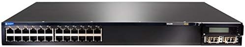
Figure 4.1: Front Panel of EX4200-24P Switch. This image displays the front of the Juniper Networks EX4200-24P switch, featuring 24 RJ-45 Gigabit Ethernet ports, each with LED indicators, and four SFP+ uplink ports on the right side, along with a small LCD display and control buttons.
The front panel of the EX4200-24P switch includes:
- 24 ports Ethernet 10/100/1000BASE-T : RJ-45 connectors for network devices. Each port supports Power over Ethernet Plus (PoE+).
- LED d'état des ports : Indicators for link status, activity, and PoE status for each port.
- Uplink Module Slot: Typically houses 4x SFP/SFP+ ports for high-speed uplinks to other network devices or the core network.
- Écran LCD : Provides system status, configuration information, and error messages.
- Boutons de contrôle : Used to navigate and interact with the LCD display menu.
- Voyants d'état du système : Indicators for power, alarm, and system status.
4.2 Panneau arrière

Figure 4.2 : Angulaire View of EX4200-24P Switch. This image provides an angled perspective of the Juniper Networks EX4200-24P switch, highlighting the front panel with its 24 Ethernet ports and uplink module, and giving a partial view of the side chassis. The rear panel, not fully visible in this image, typically contains power input, fan modules, and a console port.
Le panneau arrière comprend généralement :
- Connecteur d'alimentation CA : Pour brancher le cordon d'alimentation.
- Port console (RJ-45) : For local management and initial configuration using a serial connection.
- Port USB : For software upgrades or configuration backup/restore.
- Modules de ventilateur : Removable fan trays for cooling.
5. Configuration et installation
5.1 Préparation du site
Before installation, ensure the installation site meets the following requirements:
- Environnement: Maintain an ambient temperature between 0°C and 45°C (32°F and 113°F) and relative humidity between 10% and 85% (non-condensing).
- Pouvoir: A dedicated power outlet with proper grounding is recommended.
- Ventilation: Ensure at least 5 cm (2 inches) of clearance at the front and rear for airflow.
5.2 Montage en rack
The EX4200-24P is designed for installation in a standard 19-inch equipment rack.
- Fixez les supports de montage en rack fournis sur les côtés du commutateur à l'aide des vis fournies.
- Alignez le commutateur avec les montants du rack et fixez-le à l'aide des vis de rack appropriées.
5.3 Connexion d'alimentation
- Connect one end of the power cord to the AC power connector on the rear panel of the switch.
- Branchez l'autre extrémité du cordon d'alimentation à une prise électrique mise à la terre.
- The switch will power on automatically. Observe the system status LEDs for initial boot-up.
5.4 Connexions réseau
- Connect Ethernet cables from your network devices (computers, IP phones, wireless access points) to the RJ-45 ports on the front panel.
- For uplink connections to other switches or routers, insert appropriate SFP/SFP+ transceivers into the uplink module slot and connect fiber or copper cables as required.
- For initial configuration, connect a console cable from your management workstation to the console port on the rear panel.
6. Utilisation de l'interrupteur
6.1 Mise sous tension et démarrage initial
Once connected to power, the switch will begin its boot sequence. The system status LEDs will indicate the boot progress. The LCD display will show system information during startup.
6.2 Indicateurs LED
Surveillez les voyants du panneau avant pour connaître l'état de fonctionnement de l'interrupteur :
- Voyant système : Indicates overall system health (e.g., green for normal operation, amber for minor alarm, red for major alarm).
- Voyant d'alimentation : Indique l'état de l'alimentation.
- Voyants LED de liaison/activité des ports :
- Vert uni : Lien établi.
- Vert clignotant : Activity on the port.
- Désactivé: Pas de lien.
- Voyants d'état PoE : Indicate Power over Ethernet status for PoE-enabled ports.
6.3 Accès à la configuration de base
The switch can be configured via the command-line interface (CLI) through the console port or remotely via Telnet/SSH after initial IP configuration. Refer to the Juniper Networks documentation for detailed CLI commands and configuration guides.
- Port de console : Use a terminal emulator (e.g., PuTTY) with settings: 9600 baud, 8 data bits, no parity, 1 stop bit, no flow control.
- Web Interface: Some Juniper switches offer a web-based management interface. Check your specific firmware version for availability and default access details.
7. Entretien
7.1 Nettoyage
Un nettoyage régulier permet de maintenir des performances optimales et prolonge la durée de vie de l'interrupteur.
- Power off and disconnect the switch before cleaning.
- Utilisez un chiffon doux et sec pour essuyer l'extérieur.
- Use compressed air to clear dust from ventilation openings and fan modules.
- N’utilisez pas de nettoyants liquides ou en aérosol directement sur l’interrupteur.
7.2 mises à jour du micrologiciel
Consultez régulièrement le support de Juniper Networks website for the latest firmware updates. Firmware updates can provide new features, performance improvements, and security patches. Follow the instructions provided with the firmware package for proper installation.
7.3 Considérations environnementales
Ensure the switch operates within its specified temperature and humidity ranges. Avoid blocking ventilation ports and ensure proper airflow to prevent overheating, which can lead to system instability or failure.
8. Dépannage
Cette section propose des solutions aux problèmes courants que vous pourriez rencontrer.
8.1 Pas d'alimentation
- Vérifiez que le cordon d'alimentation est bien branché à la fois à l'interrupteur et à la prise électrique.
- Vérifiez si la prise de courant fonctionne en y branchant un autre appareil.
- Ensure the power supply unit (if modular) is properly seated.
8.2 Aucun lien sur le port
- Vérifiez la connexion du câble Ethernet aux deux extrémités. Essayez un autre câble.
- Vérifiez que l'appareil connecté est allumé et fonctionne correctement.
- Check the port configuration on the switch (e.g., speed, duplex settings).
8.3 Problèmes de connectivité réseau
- Confirm the switch has a valid IP address and network configuration.
- Vérifiez les conflits d'adresses IP sur le réseau.
- Verify VLAN configurations if applicable.
- Redémarrez le commutateur et les appareils connectés.
8.4 Réinitialisation d'usine
A factory reset will erase all configurations and restore the switch to its default settings. Consult the Juniper Networks documentation for the specific procedure for the EX4200 series, as it typically involves a specific command sequence via the console port.
9. Spécifications techniques
| Fonctionnalité | Spécification |
|---|---|
| Modèle | EX4200-24P |
| Marque | Réseaux Juniper |
| Nombre de ports | 24 x 10/100/1000BASE-T (PoE+) |
| Type d'interface | RJ45 |
| Dimensions du produit (L x l x H) | 23 x 22.75 x 11 pouces (58.42 x 57.78 x 27.94 cm) |
| Poids de l'article | 23.1 livres (10.48 kg) |
| Matériau du boîtier | Plastique |
| Indice de température supérieur | 45 degrés Celsius |
| Code UPC | 647213692099 |
| ASIN | B07PFLPRX6 |
10. Informations sur la garantie
This Juniper Networks EX4200-24P switch is offered as a renewed product. Warranty coverage for renewed products is typically provided by the seller, "Network Hardware Depot" in this case, or the Amazon Renewed program, not directly by Juniper Networks.
- Seller's Return Policy: The seller offers a return policy, typically 30 days for refund/replacement.
- Plans de protection prolongée : Additional protection plans may be available for purchase through Amazon or third-party providers.
- For specific warranty details and terms, please refer to the purchase agreement or contact the seller directly.
Legal Disclaimer from Seller: "We DO NOT accept RMA's or Returns for Non Defective Items. Any merchandise returned for repair and found NOT to be defective by our technicians will have a 25% restocking fee. There will be no exception to this policy. By placing a bid or order with us you have entered into a binding agreement that you acknowledge and accept our procedures. Additional warranty length is available, contact us directly for more details."
11. Assistance
For technical assistance, further documentation, or advanced configuration guides, please refer to the official Juniper Networks support website. For issues related to the renewed product's condition or seller-specific policies, contact the seller directly.
- Assistance Juniper Networks : www.juniper.net/us/en/support.html
- Contact du vendeur : Refer to your Amazon order details for seller contact information (Network Hardware Depot).


