1. Introduction
This manual provides detailed instructions for the installation, operation, and maintenance of the Novastar MCTRL300 Synchronous LED Sender Box. Please read this manual thoroughly before using the device to ensure proper functionality and to prevent damage.
The Novastar MCTRL300 is a high-performance LED display controller designed for full-color LED screens, offering reliable and stable operation for various indoor and outdoor applications.
2. Produit terminéview et fonctionnalités
The Novastar MCTRL300 is a full-color sending card and LED display accessory. It is engineered to manage LED displays with high efficiency and precision.
Caractéristiques principales :
- Entrée DVI : One (1) DVI input for video signal connection.
- Entrée audio : Supports external audio input.
- Sortie de données : Two (2) RJ45 ports for data output, supporting hot backup functionality for enhanced reliability.
- Interface de contrôle : USB control interface, allowing for cascading multiple units.
- Capacité en pixels : Supports up to 1.3 million pixels.
- Résolutions prises en charge : Includes 1280×1024, 1024×1200, 1600×848, 1920×712, 2048×668, and custom resolutions.
- Light Sensor Interface: One (1) interface for automatic brightness adjustment based on ambient light conditions.
- Application: Suitable for both indoor and outdoor full-color RGB LED display control.
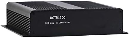
Figure 2.1 : Face avant view of the Novastar MCTRL300 LED Sender Box, showing the model name.
3. Installation et connexions
This section details the physical connections required to set up your Novastar MCTRL300 LED Sender Box.
3.1 Panneau arrière surview

Figure 3.1: Rear panel of the MCTRL300, illustrating power input, DVI, USB, audio, UART, and RJ45 data output ports.
- Power Input (AC 100-240V ~ 50/60Hz): Connect the provided power cable to this port and to a suitable power outlet. The power switch is located next to this port.
- Entrée DVI : Connect your video source (e.g., PC graphics card) to this port using a DVI cable.
- Port USB : Connect a USB cable from your control PC to this port for device configuration and control.
- Entrée audio : Connect an external audio source if audio transmission is required.
- RJ45 Data Output (OUT1, OUT2): Connect standard Ethernet cables from these ports to the receiving cards of your LED display. OUT1 and OUT2 support hot backup.
- UART IN/OUT: Used for cascading multiple sender boxes or for specific control scenarios.
- Capteur de lumière : Connect an external light sensor for automatic brightness adjustment.
3.2 Schéma de connexion
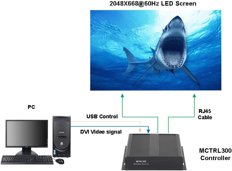
Figure 3.2: Typical connection setup for the MCTRL300, illustrating DVI video signal, USB control, and RJ45 data output to an LED screen.
- Connect the DVI output from your PC's graphics card to the DVI input port on the MCTRL300.
- Connect a USB cable from your PC to the USB port on the MCTRL300. This enables software control and configuration.
- Connect one or more RJ45 Ethernet cables from the MCTRL300's OUT1/OUT2 ports to the input ports of the first receiving card in your LED display panel chain. Ensure proper cabling for the entire LED screen.
- Connect the power cable to the MCTRL300 and a power source.
- Turn on the power switch on the rear panel of the MCTRL300. The "RUN" and "STATUS" indicators will illuminate.
4. Mode d'emploi
After completing the physical connections, the MCTRL300 is ready for operation. Configuration and content management are typically performed using dedicated software on the connected PC.
- Mise sous tension : Ensure all connections are secure, then switch on the power to the MCTRL300 using the rear panel switch.
- Configuration du logiciel: Use the Novastar control software on your PC to detect the MCTRL300. Configure the LED display parameters, including resolution, screen mapping, and brightness settings. Refer to the software's user guide for detailed instructions.
- Lecture de contenu : Once configured, the MCTRL300 will transmit the video signal from your PC to the LED display. Ensure your PC's display settings match the configured resolution for optimal output.
- Réglage de la luminosité : If a light sensor is connected, the display brightness can be automatically adjusted. Manual adjustment is also possible via the control software.
5. Entretien
Proper maintenance ensures the longevity and reliable performance of your MCTRL300 LED Sender Box.
- Nettoyage: Nettoyez régulièrement l'extérieur de l'appareil avec un chiffon doux et sec. Évitez d'utiliser des nettoyants liquides ou des solvants. Assurez-vous que les ouvertures de ventilation sont exemptes de poussière et de débris.
- Conditions environnementales : Operate the device within its specified temperature and humidity ranges. Avoid exposure to extreme temperatures, direct sunlight, or high moisture environments.
- Gestion des câbles: Ensure all cables are securely connected and not under strain. Periodically check for any signs of wear or damage to cables.
- Mises à jour logicielles : Keep the Novastar control software and device firmware updated to the latest versions for optimal performance and compatibility.
6. Dépannage
This section provides solutions to common issues you might encounter with the MCTRL300.
| Problème | Cause possible | Solution |
|---|---|---|
| No display on LED screen. |
|
|
| "RUN" or "STATUS" indicator not lit. |
|
|
| Display shows abnormal colors or flickering. |
|
|
If the problem persists after attempting these solutions, please contact Novastar technical support.
7. Spécifications
Technical specifications for the Novastar MCTRL300 LED Sender Box.
| Fonctionnalité | Détail |
|---|---|
| Marque | Novastar |
| Modèle | MCTRL300 |
| Interface d'entrée | 1 x DVI, External Audio |
| Interface de sortie | 2 x RJ45 (Data Output, Hot Backup), UART OUT |
| Interface de contrôle | 1 x USB, UART IN |
| Pixel Capacity | 1.3 million de pixels |
| Résolutions prises en charge | 1280×1024, 1024×1200, 1600×848, 1920×712, 2048×668, or custom |
| Caractéristiques spéciales | Light Sensor Interface for auto brightness adjustment, Cascading support via USB |
| Alimentation électrique | CA 100-240V ~ 50/60Hz |
| Poids de l'article | 3.88 livre (environ 1.76 kg) |
| Dimensions du colis | 11.1 x 8.54 x 4.57 pouces (environ 28.2 x 21.7 x 11.6 cm) |

Figure 7.1: MCTRL300 package contents, including the sender box and necessary cables.
8. Assistance
For further assistance, technical support, or warranty inquiries, please refer to the official Novastar webconsultez votre site web ou contactez votre revendeur agréé.
Always ensure you have your product model number (MCTRL300) and purchase details available when contacting support.