1. Introduction
This manual provides detailed instructions for the installation, operation, and maintenance of the Cotek SP-1000-224 Pure Sine Wave Inverter. This inverter is designed to convert 24VDC power to 230VAC, providing a stable and reliable power source for various applications.
Caractéristiques principales :
- Sortie sinusoïdale pure pour les appareils électroniques sensibles.
- Fonction de commande à distance marche/arrêt (borne verte).
- Entrée et sortie entièrement isolées pour une sécurité accrue.
- Ventilateur de refroidissement à température et charge contrôlées pour des performances optimales.
- Interface conviviale.
- Fréquence de sortie (50/60 Hz) sélectionnable via un commutateur DIP.
- Volume de sortietagsélectionnable via un commutateur DIP.
- Mode d'économie d'énergie réglable via une résistance variable.
- 3-color LED status indicators for easy monitoring.
- Protection complète des entrées : inversion de polarité (fusible), sous-tensiontage, plus de voltage.
- Protection robuste en sortie : court-circuit, surcharge, surchauffe.
- Boîtier intérieur en aluminium de type 1.
- Approuvé E13 / UL / CE / FCC.
2. Consignes de sécurité
WARNING: Please read and understand all safety instructions before installing or operating this inverter. Failure to follow these instructions may result in electric shock, fire, serious injury, or death.
- Risque électrique : This unit produces high voltage. Do not open the inverter casing. Confiez toutes les interventions de maintenance à un personnel qualifié.
- Sécurité des batteries : Work in a well-ventilated area. Batteries can produce explosive gases. Do not smoke or allow sparks or flames near the battery.
- Ventilation adéquate : Ensure adequate airflow around the inverter. Do not block ventilation openings.
- Conditions environnementales : Do not expose the inverter to rain, moisture, or excessive dust. Operate in a dry, cool environment.
- Mise à la terre : The inverter must be properly grounded. Follow all local and national electrical codes.
- Capacité de charge: Ne dépassez pas la puissance nominale de l'onduleur. Une surcharge peut endommager l'onduleur et les appareils qui y sont connectés.
- Avertissement concernant la Proposition 65 de Californie : Ce produit peut contenir des substances faisant l'objet d'avertissements en vertu de la Proposition 65 de Californie.
3. Produit terminéview et composants
Familiarize yourself with the various parts of your Cotek SP-1000-224 Pure Sine Wave Inverter.

Figure 3.1 : Incliné view of the Cotek SP-1000-224 Pure Sine Wave Inverter, showing its blue aluminum casing and grey end caps with ventilation and connection ports.

Figure 3.2 : Front panel of the inverter, featuring the AC output socket (Schuko type), a power switch, LED indicators, and DIP switches for configuration.

Figure 3.3 : Rear panel of the inverter, showing the DC input terminals for battery connection, a remote control port (RJ45), and a green terminal block for remote ON/OFF control.

Figure 3.4 : Côté view of the inverter, highlighting its robust blue aluminum heat sink casing conçu pour une dissipation thermique efficace.
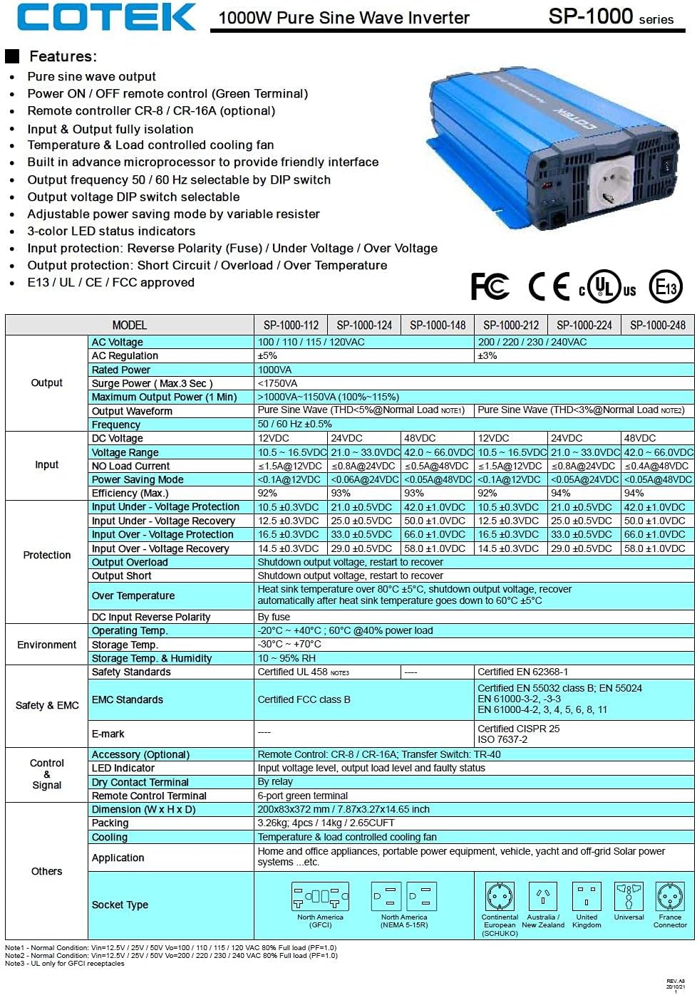
Figure 3.5 : A detailed table outlining the features and technical specifications of the Cotek SP-1000 series inverters, including input/output parameters, protections, and certifications.

Figure 3.6 : Mechanical drawings providing dimensions of the inverter, along with power voltage and power temperature curves illustrating performance characteristics.
4. Configuration et installation
4.1 Choix d'un emplacement :
- Installez l'onduleur dans un endroit sec, frais et bien ventilé.
- Évitez la lumière directe du soleil, les sources de chaleur et l'humidité.
- Ensure sufficient clearance around the inverter for proper airflow, especially around the cooling fan and ventilation openings.
- Mount the inverter securely on a stable, non-combustible surface.
4.2 DC Input Connection:
- Assurez-vous que l'interrupteur d'alimentation de l'onduleur est en position OFF.
- Connect the positive (+) terminal of the 24VDC battery bank to the positive (+) DC input terminal on the inverter.
- Connect the negative (-) terminal of the 24VDC battery bank to the negative (-) DC input terminal on the inverter.
- Utilisez des câbles de taille appropriée pour minimiser le volumetage drop and ensure safe operation. Refer to electrical standards for cable sizing.
- Assurez-vous que toutes les connexions sont serrées et sécurisées.
4.3 AC Output Connection:
- Plug your AC appliances directly into the AC output socket on the inverter.
- Ensure the total power consumption of all connected appliances does not exceed the inverter's 1000W continuous output rating.
4.4 Mise à la terre :
Proper grounding is essential for safety. Connect the inverter's chassis ground terminal to a reliable earth ground using a suitable grounding wire. Consult local electrical codes for specific grounding requirements.
4.5 Remote Control (Optional):
The inverter supports remote ON/OFF control via the green terminal block or an optional RJ45 remote control unit. Refer to the accessory manual for detailed instructions on connecting and using the remote control.
4.6 Configuration des commutateurs DIP :
The inverter features DIP switches on the front panel to select output frequency (50/60 Hz) and output voltage. Refer to the table below for common settings. Ensure the inverter is OFF before changing DIP switch settings.
| Paramètre | Position du commutateur DIP |
|---|---|
| Fréquence de sortie 50Hz | Switch 1: OFF, Switch 2: OFF (Example, refer to actual product manual/Figure 3.5) |
| Fréquence de sortie 60Hz | Switch 1: ON, Switch 2: OFF (Example, refer to actual product manual/Figure 3.5) |
| Volume de sortietaget 230VAC | Switch 3: ON, Switch 4: OFF (Example, refer to actual product manual/Figure 3.5) |
Note: The exact DIP switch configurations for specific voltage and frequency settings are detailed in the product's full technical specifications (refer to Figure 3.5). Always verify settings before operation.
5. Fonctionnement
5.1 Powering On the Inverter:
- Ensure all DC and AC connections are secure and correct.
- If using the remote control, ensure it is connected and in the ON position.
- Flip the main power switch on the inverter's front panel to the "ON" position.
- Observe the 3-color LED status indicators. A green light indicates normal operation.
5.2 LED Status Indicators:
- Vert: Fonctionnement normal.
- Jaune/Ambre : Warning (e.g., input voltage slightly low/high, minor overload). The inverter may continue to operate but requires attention.
- Rouge: Fault condition (e.g., severe overload, short circuit, over-temperature, critical input voltage). The inverter will shut down to protect itself and connected devices.
5.3 Power Saving Mode:
The inverter features a power saving mode, adjustable via a variable resistor. This mode reduces power consumption when no load or a very light load is detected. Adjust the resistor to set the sensitivity for entering/exiting power saving mode.
5.4 Powering Off the Inverter:
- Turn off all connected AC appliances.
- Flip the main power switch on the inverter's front panel to the "OFF" position.
- If using a remote control, turn it off as well.
6. Entretien
Un entretien régulier garantit la longévité et le fonctionnement fiable de votre onduleur.
- Nettoyage: Nettoyez régulièrement l'extérieur de l'onduleur avec un chiffon doux et sec. N'utilisez pas de nettoyants liquides ni de solvants. Assurez-vous que les ouvertures de ventilation sont exemptes de poussière et de débris.
- Relations: Periodically check all DC and AC connections to ensure they are tight and free from corrosion. Loose connections can cause overheating and poor performance.
- Ventilation: Ensure the cooling fan and ventilation grilles are not obstructed. The fan operates based on temperature and load, so ensure it can draw and expel air freely.
- État de la batterie : Monitor the health of your battery bank. A weak or failing battery can negatively impact inverter performance and lifespan.
WARNING: Do not attempt to service the inverter yourself. There are no user-serviceable parts inside. Refer all servicing to qualified personnel.
7. Dépannage
This section provides solutions to common issues you might encounter with your inverter. If the problem persists after following these steps, contact customer support.
| Problème | Cause possible | Solution |
|---|---|---|
| Inverter does not turn on (No LED indication) |
|
|
| Red LED is on, inverter shuts down |
|
|
| Yellow/Amber LED is on |
|
|
| Pas de sortie CA |
|
|
8. Spécifications techniques
The following table provides detailed technical specifications for the Cotek SP-1000-224 Pure Sine Wave Inverter. For a comprehensive overview, refer to Figure 3.5.
| Paramètre | Value (SP-1000-224) |
|---|---|
| Modèle | SP-1000-224 |
| Vol de sortie CAtage | 230VAC (selectable) |
| Vol d'entrée CCtage | 24 V CC |
| Puissance continue | 1000 W |
| Surge Power (3 sec) | 1750 VA |
| Forme d'onde de sortie | Onde sinusoïdale pure (THD < 3%) |
| Fréquence de sortie | 50/60 Hz (sélectionnable) |
| Efficacité (max.) | 92% |
| Entrée sous voltaget protection | 21.0 ± 0.5 VCC |
| Entrée sur voltaget protection | 33.0 ± 0.5 VCC |
| Température de fonctionnement | -20°C ~ +40°C (60% power load) |
| Dimensions (L x l x H) | 17 x 10 x 6 pouces (environ) |
| Poids | 8.94 livres |
| Certifications | Approuvé E13 / UL / CE / FCC |
Note: Specifications are subject to change without notice. Always refer to the product label or manufacturer's official documentation for the most accurate and up-to-date information.
9. Informations sur la garantie
COTEK products are manufactured to high quality standards. For specific warranty terms and conditions, including duration and coverage, please refer to the warranty card included with your product or visit the official COTEK webConsultez le site. Conservez votre preuve d'achat pour toute réclamation au titre de la garantie.
Typical warranties cover defects in materials and workmanship under normal use. Damage caused by improper installation, misuse, abuse, or unauthorized modifications is generally not covered.
10. Assistance clientèle
If you have any questions, require technical assistance, or need to report an issue with your Cotek SP-1000-224 Pure Sine Wave Inverter, please contact COTEK customer support or your authorized dealer.
Lorsque vous contactez l'assistance, veuillez préparer les informations suivantes :
- Product Model: SP-1000-224
- Serial Number (if applicable, usually found on the product label)
- Date d'achat
- Une description détaillée du problème que vous rencontrez.
For the most up-to-date contact information, please visit the official COTEK website: www.cotek.com.tw (Ceci est un espace réservé) URLVeuillez vérifier le fabricant réel. webplacer).


