1. Introduction
This manual provides essential information for the safe and efficient operation of your VOLTCRAFT GOS-632 FG Oscilloscope with Frequency Generator. Please read this manual thoroughly before using the device and keep it for future reference. The GOS-632 FG is a 30 MHz dual-channel analog oscilloscope integrated with a frequency generator, designed for various electronic measurement and testing applications.
2. Consignes de sécurité
Respectez toujours les consignes de sécurité suivantes afin d'éviter tout choc électrique, blessure ou dommage à l'instrument :
- Source d'alimentation : Connect the instrument only to a power source with the specified voltage et fréquence.
- Mise à la terre : Assurez-vous que l'instrument est correctement mis à la terre afin d'éviter tout risque d'électrocution.
- Ventilation: Do not block ventilation openings. Ensure adequate airflow to prevent overheating.
- Environnement: Operate the oscilloscope in a dry, clean environment, away from direct sunlight, high temperatures, and excessive dust or humidity.
- Sondes: Utilisez uniquement des sondes adaptées au volumetage and frequency being measured. Ensure probes are in good condition.
- Entretien: Refer all servicing to qualified service personnel. Do not attempt to open or repair the instrument yourself.
- Contact avec un liquide : Avoid contact with liquids. If liquid enters the device, disconnect power immediately and have it inspected by a qualified technician.
3. Contenu du colis
Please check the package contents upon receipt. If any items are missing or damaged, contact your dealer immediately.
- VOLTCRAFT GOS-632 FG Oscilloscope with Frequency Generator
- Cordon d'alimentation
- Two (2) Oscilloscope Probes (1x/10x switchable)
- Manuel de l'utilisateur (ce document)
4. Produit terminéview
The VOLTCRAFT GOS-632 FG is a robust analog oscilloscope designed for reliable waveform analysis. Below is a general view de l'appareil.
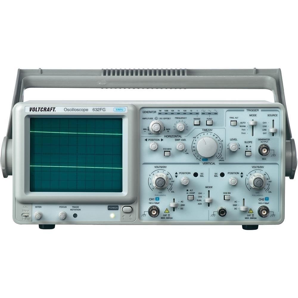
Figure 4.1 : Devant view of the VOLTCRAFT GOS-632 FG Oscilloscope. This image shows the main display, control knobs, and input connectors for the two channels and the frequency generator output.
4.1. Commandes du panneau avant
- CRT Display: Shows the waveform.
- Entrée CH1/CH2 : Connecteurs BNC pour le raccordement des sondes d'oscilloscope.
- VOLTS/DIV: Adjusts the vertical sensitivity for each channel.
- POSITION: Adjusts the vertical position of the waveform.
- TIME/DIV: Adjusts the horizontal sweep speed.
- TRIGGER LEVEL: Définit le volumetage level at which the sweep starts.
- MODE: Selects trigger source (CH1, CH2, EXT, LINE).
- FREQUENCY GENERATOR OUTPUT: BNC connector for the integrated signal generator.
- FREQUENCY/AMPLITUDE : Controls for the frequency generator output.
- Interrupteur: Allume ou éteint l'appareil.
4.2. Connexions du panneau arrière
- Entrée de courant alternatif: Connecteur pour le cordon d'alimentation.
- Borne au sol : For additional grounding if required.
5. Installation
- Déballage: Carefully remove the oscilloscope from its packaging. Retain the packaging for future transport.
- Placement: Place the oscilloscope on a stable, level surface with adequate ventilation around the unit.
- Connexion électrique : Connect the supplied power cord to the AC power input on the rear panel and then to a grounded electrical outlet.
- Connexion de la sonde : Connect the oscilloscope probes to the CH1 and/or CH2 BNC input connectors on the front panel. Ensure a secure connection.
- Compensation de la sonde : Before taking measurements, compensate your probes. Connect the probe tip to the probe compensation output (usually a square wave signal on the front panel) and adjust the probe's compensation trimmer until a flat-top square wave is displayed.
6. Utilisation de l'oscilloscope
6.1. Mesures de base
- Mise sous tension : Press the POWER switch to turn on the oscilloscope. Allow a few minutes for the display to stabilize.
- Signal d'entrée: Connect the probe to the circuit point you wish to measure.
- Vertical Adjustment (VOLTS/DIV & POSITION):
- Select the appropriate VOLTS/DIV setting to display the waveform within the screen.
- Use the POSITION knob to center the waveform vertically.
- Horizontal Adjustment (TIME/DIV & POSITION):
- Select the appropriate TIME/DIV setting to display several cycles of the waveform horizontally.
- Use the horizontal POSITION knob to move the waveform left or right.
- Configuration du déclencheur :
- Set the TRIGGER MODE (e.g., AUTO, NORM).
- Adjust the TRIGGER LEVEL knob until a stable waveform is displayed.
- Select the TRIGGER SOURCE (e.g., CH1, CH2).
6.2. Using the Frequency Generator
- Sortie de connexion : Connect a BNC cable from the FREQUENCY GENERATOR OUTPUT to the circuit or device under test.
- Définir la fréquence : Use the FREQUENCY control to select the desired output frequency.
- Ensemble Amplitude : Utilisez le AMPLITUDE control to adjust the output signal strength.
- Sélection de la forme d'onde : If available, select the desired waveform type (e.g., sine, square, triangle).
7. Entretien
- Nettoyage: Débranchez le cordon d'alimentation avant le nettoyage. Utilisez un chiffon doux et sec.amp cloth with a mild detergent to clean the exterior. Do not use abrasive cleaners or solvents.
- Stockage: When not in use for extended periods, store the oscilloscope in a dry, dust-free environment.
- Étalonnage: For accurate measurements, periodic calibration by qualified personnel is recommended.
8. Dépannage
| Problème | Cause possible | Solution |
|---|---|---|
| Pas d'affichage après la mise sous tension | No power, brightness/focus too low | Check power cord, outlet. Adjust INTENSITY and FOCUS knobs. |
| Forme d'onde instable | Incorrect trigger settings, signal too noisy | Adjust TRIGGER LEVEL, TRIGGER MODE, and TRIGGER SOURCE. Check signal integrity. |
| Aucun signal affiché | Probe not connected, incorrect VOLTS/DIV, signal outside range | Ensure probe is connected and making contact. Adjust VOLTS/DIV and POSITION. Check probe compensation. |
| Frequency generator output not working | Output cable not connected, amplitude set to zero | Check output cable connection. Increase AMPLITUDE. |
9. Spécifications
| Fonctionnalité | Détail |
|---|---|
| Numéro de modèle | GOS-632 FG |
| Fabricant | VOLTCRAFT |
| Bande passante | 30 MHz (DC) |
| Chaînes | 2 canaux analogiques |
| Integrated Function | Générateur de fréquence |
| Poids du produit | 9.07 g (Note: This weight seems unusually low for an oscilloscope and might be a data entry error. Refer to product packaging for accurate weight.) |
| ASIN | B003IDBEYM |
| Premier disponible | 31er mars 2015 |
10. Garantie et assistance
VOLTCRAFT products are designed for quality and reliability. For information regarding warranty terms, technical support, or service, please refer to the warranty card included with your product or visit the official VOLTCRAFT website. N'essayez pas de réparer l'appareil vous-même, car cela pourrait annuler votre garantie.
For further assistance, please contact your local VOLTCRAFT distributor or customer service center.


