
1. Introduction
The ELEGOO ESP-32 Super Starter Kit provides a comprehensive platform for learning about electronics, programming, and the Internet of Things (IoT). At its core is the powerful ESP-32 development board, featuring a dual-core processor, integrated Wi-Fi, and Bluetooth 4.2. This kit is designed for students, makers, engineers, and hobbyists of all skill levels, offering a wide array of components and a detailed online tutorial to guide you through various projects.
The ESP-32 board is fully compatible with the Arduino IDE, making programming accessible and straightforward. With over 35 different modules and electronic components, you can build projects ranging from basic circuits to advanced IoT applications like weather stations, smart home controllers, and remote-controlled devices.

Figure 1.1: The ELEGOO ESP-32 Super Starter Kit, showcasing the main components and a sample project setup.
2. Contenu du kit
This kit includes a wide variety of electronic components and modules to facilitate diverse projects. Below is a detailed list of the items you will find in your ELEGOO ESP-32 Super Starter Kit.

Figure 2.1 : Un aperçu complet view of the components included in the kit.
2.1 Liste des composants
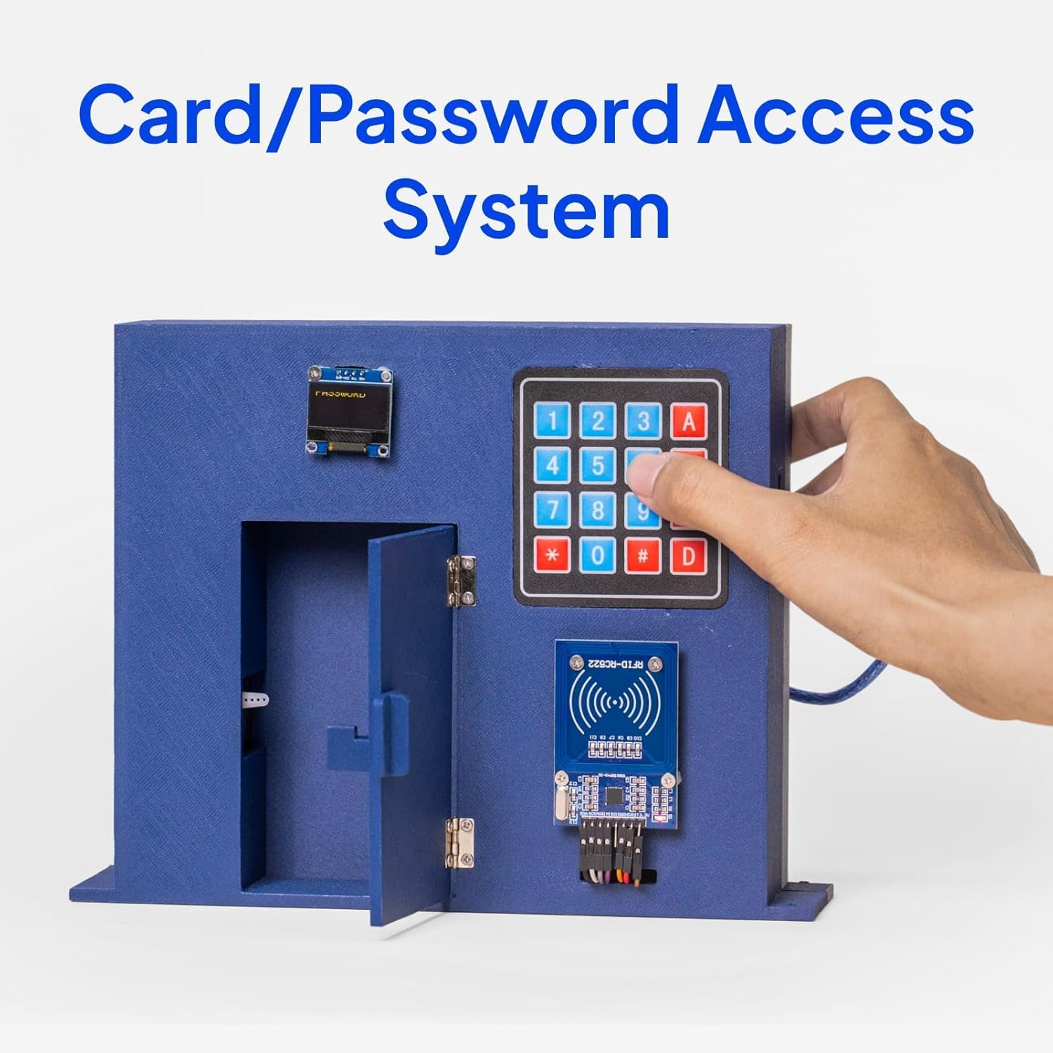
Figure 2.2: Visual representation of the kit's extensive component list.
| Composant | Quantité |
|---|---|
| ESP-32 Board | 1 PC |
| Module GY-6500 | 1 PC |
| 0.96 inch OLED Display Module | 1 PC |
| Module d'alimentation électrique | 1 PC |
| ULN2003 Stepper Motor Driver Module | 1 PC |
| Moteur pas à pas | 1 PC |
| 9V Battery with Snap-on Connector Clip | 1 PC |
| Relais 5V | 1 PC |
| Capteur à ultrasons | 1 PC |
| Fan Blade and 3-6V Motor | 1 PC |
| Buzzer actif | 1 PC |
| Buzzer passif | 1 PC |
| 74HC595 IC | 1 PC |
| L293D IC | 1 PC |
| Module RFID RC522 | 1 PC |
| HC-SR501 PIR Motion Sensor Module | 1 PC |
| Membrane Switch Module | 1 PC |
| Bouton | 5 pièces |
| Potentiomètre 10K | 1 PC |
| 1 Digit 7-Segment Display | 1 PC |
| 4 Digit 7-Segment Display | 1 PC |
| Tilt Ball Switch | 1 PC |
| Télécommande | 1 PC |
| 400 Tie-Point Breadboard | 2 pièces |
| Câble USB A vers C | 1 PC |
| Cavalier | 65 pièces |
| Servo Motor SG90 | 1 PC |
| IR Receiver Module | 1 PC |
| IR Emission Module | 1 PC |
| Module de joystick | 1 PC |
| DHT11 Temperature and Humidity Module | 1 PC |
| Female-to-Male Dupont Wire | 10 pièces |
| Résistance | 120 pièces |
| DIRIGÉ | 25 pièces |
| LED RVB | 2 pièces |
| thermistance | 1 PC |
| Diode Rectifier | 2 pièces |
| Photoresistor (Photocell) | 2 pièces |
| NPN Transistor PN2222 | 2 pièces |

Figure 2.3: The organized storage box for the kit components.
3. Installation
3.1 ESP-32 Board Connection
The ESP-32 board is the central component of this kit. It features a USB-C port for power and data communication. To begin, connect the ESP-32 board to your computer using the provided USB A to C cable.

Figure 3.1: The ESP-32 board with its USB-C connection.
3.2 Software Installation (Arduino IDE)
- Download Arduino IDE: Visitez le site officiel d'Arduino website (www.arduino.cc/en/software) and download the latest version of the Arduino IDE for your operating system.
- Install ESP-32 Board Support: Follow the instructions in the online tutorial to add ESP-32 board support to your Arduino IDE. This typically involves adding a board manager URL in preferences and then installing the ESP32 boards package.
- Installez le pilote USB : The ESP-32 board uses a CP2102 USB-to-UART bridge chip. If your operating system does not automatically install the necessary driver, you may need to download and install it manually from the Silicon Labs website.
- Sélectionner la carte et le port : Dans l'IDE Arduino, accédez à Outils > Tableau and select the appropriate ESP-32 Dev Module. Then, go to Outils > Port and select the serial port corresponding to your connected ESP-32 board.
3.3 Utilisation de la plaque d'essai
The kit includes breadboards for easy prototyping without soldering. The ESP-32 board is designed to fit onto standard breadboards. It is recommended to use two breadboards side-by-side to provide ample space for connections.
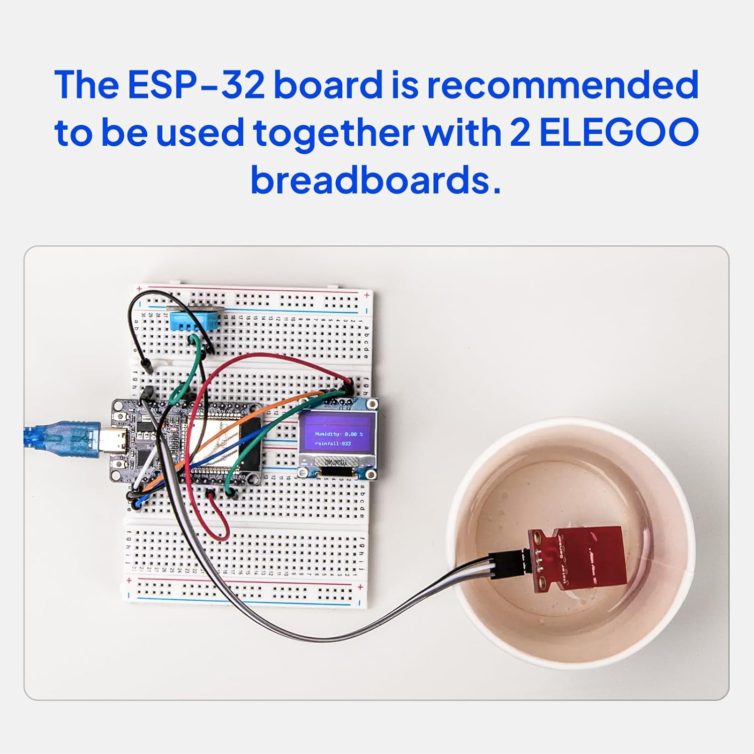
Figure 3.2: ESP-32 board connected to breadboards for a project.
4. Mode d'emploi
The ELEGOO ESP-32 Super Starter Kit comes with a detailed online tutorial that provides step-by-step instructions for over 30 projects. This section outlines general operating principles.
4.1 Accessing the Online Tutorial
Refer to the Quick Start Guide included in your kit for instructions on how to access the online tutorial. The tutorial includes complete code, clear circuit diagrams, and explanations for each project.
4.2 Basic Project Workflow
- Review Schéma: Before connecting any components, carefully study the circuit diagram provided in the tutorial for your chosen project.
- Assemble Hardware: Connect the components to the ESP-32 board on the breadboard according to the circuit diagram. Ensure all connections are secure and correctly oriented.
- Code de téléchargement : Open the provided example code in the Arduino IDE. Verify the code for errors, then upload it to your ESP-32 board.
- Test and Observe: After successful upload, test the project functionality. Use the Serial Monitor in Arduino IDE for debugging and observing output if applicable.
4.3 Example Projets
The tutorial guides you through building various practical applications:
- Station météo: Utilize sensors to measure environmental data like temperature and humidity, displaying it on an OLED screen or sending it to the cloud.
- Card/Password Access System: Implement security features using RFID modules and keypads.
- Retro Snake Game: Develop interactive games using the OLED display and joystick module.
Figure 4.1: Weather Station project example.

Figure 4.2: Card/Password Access System project example.

Figure 4.3: Retro Snake Game project example.
5. Entretien
Proper care and maintenance will ensure the longevity and optimal performance of your ELEGOO ESP-32 Super Starter Kit components.
- Stockage: Store all components in the provided organized box in a cool, dry place away from direct sunlight and extreme temperatures.
- Manutention: Handle electronic components, especially integrated circuits (ICs) and the ESP-32 board, with care. Avoid touching pins directly to prevent damage from electrostatic discharge (ESD).
- Nettoyage: Si nécessaire, nettoyez délicatement les composants avec un chiffon doux et sec. Évitez d'utiliser des liquides ou des nettoyants abrasifs.
- Alimentation: Assurez-vous toujours que le volume est correct.tage and current are supplied to the ESP-32 board and other modules. Incorrect power can cause permanent damage.
- Gestion des câbles: Keep jumper wires and cables organized to prevent tangles and accidental disconnections.
6. Dépannage
If you encounter issues while using your kit, refer to the following common troubleshooting steps:
- Carte non détectée :
- Ensure the USB cable is securely connected to both the ESP-32 board and your computer.
- Verify that the correct USB driver (CP2102) is installed.
- Check if the correct serial port is selected in the Arduino IDE (Outils > Port).
- Erreurs lors du chargement du code :
- Confirm that the correct ESP-32 board type is selected in the Arduino IDE (Outils > Tableau).
- Ensure no other applications are using the serial port.
- Try pressing the BOOT button on the ESP-32 board while uploading, if instructed by the IDE or tutorial.
- Composant non fonctionnel :
- Double-check all wiring connections against the circuit diagram. Loose or incorrect connections are common causes.
- Verify that the component is correctly oriented (e.g., LEDs, ICs).
- Ensure the component is receiving the correct power supply.
- Test the component with a known working example from the tutorial.
- Problèmes de connectivité Wi-Fi/Bluetooth :
- Ensure your Wi-Fi credentials (SSID, password) are correct in your code.
- Check that the ESP-32 is within range of your Wi-Fi network or Bluetooth device.
- Verify that the correct libraries for Wi-Fi/Bluetooth are installed in the Arduino IDE.
For more detailed troubleshooting and specific project issues, consult the online tutorial or the ELEGOO technical support resources.
7. Spécifications
Key technical specifications for the ELEGOO ESP-32 Super Starter Kit and its main components:
| Fonctionnalité | Détail |
|---|---|
| Marque | ÉLÉGOO |
| Nom du modèle | EL-KIT-032 |
| Technologie de connectivité | Bluetooth, USB, Wi-Fi |
| Compatibilité du système d'exploitation | Arduino IDE, Linux |
| Marque du processeur | Espressif |
| Nombre de processeurs | 2 (Dual-Core) |
| Technologie de mémoire RAM | RDA |
| Nombre total de ports USB | 1 (USB-C) |
| Nombre d'unités | 35.0 Count (modules/components) |
8. Informations sur la garantie
The ELEGOO ESP-32 Super Starter Kit comes with a Garantie constructeur de 1 ans. Please retain your proof of purchase for any warranty claims. For details regarding warranty terms and conditions, please refer to the official ELEGOO website ou contacter le support client.
9. Assistance
ELEGOO is committed to providing quality products and excellent customer support. If you require assistance with your kit, have technical questions, or encounter any issues, please utilize the following resources:
- Online Tutorial: The most comprehensive resource for project guides, code examples, and circuit diagrams. Access details are in your Quick Start Guide.
- Équipe d'assistance technique : ELEGOO provides a dedicated technical support team ready to assist you. Contact information can typically be found on the official ELEGOO website (www.elegoo.com).
- Communauté en ligne : Join the active ELEGOO online community for peer support, project ideas, and shared knowledge.