
1. Introduction
The AirheadStorm AT-14 is a 4-way coaxial remote antenna switch designed to simplify antenna management for amateur radio and broadcasting setups. It allows for remote switching between up to four antennas using a +12V control voltage, making it ideal for antennas mounted in elevated or remote locations such as rooftops or towers. This device supports high-power transmission environments with a continuous power handling capability of up to 500W PEP and operates across a frequency range of 1.8MHz to 60MHz. Its low-loss design ensures efficient signal transmission and clear communications.
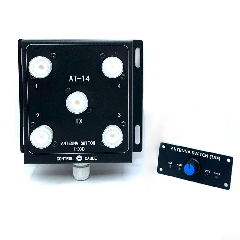
Figure 1: AirheadStorm AT-14 4-Way Coaxial Remote Antenna Switch and Controller Kit.
2. Consignes de sécurité
- Always disconnect power before making any connections or disconnections to prevent electrical shock or damage to equipment.
- Ensure all coaxial cable connections are secure and properly shielded to prevent signal leakage and interference.
- Do not exceed the specified power rating of 500W PEP to avoid damaging the switch or connected equipment.
- Install the antenna switch in a location protected from extreme weather conditions, moisture, and direct sunlight.
- Use appropriate grounding techniques for your antenna system to protect against lightning strikes and static discharge.
3. Contenu du colis
Vérifiez que tous les composants sont présents dans le package :
- 1 x AT-14 4-Way Coaxial Remote Antenna Switch Unit
- 1 x Controller Kit (includes control board with rotary switch)
4. Configuration et installation
Follow these steps for proper installation of your AT-14 antenna switch:
- Mounting the Switch Unit: Select a suitable location for the AT-14 switch unit, preferably near your antennas. This could be on a mast, tower, or other elevated structure. Ensure the mounting surface is stable and secure. The unit is designed for outdoor use but should be protected from direct heavy precipitation if possible.
- Connexion des antennes : Connect your four antennas to the SO-239 input connectors labeled 1, 2, 3, et 4 on the switch unit. Use high-quality 50 Ohm coaxial cables with PL-259 connectors.
- Connexion à la radio : Connect your radio transceiver to the SO-239 output connector labeled TX on the switch unit. Again, use a high-quality 50 Ohm coaxial cable with PL-259 connectors.
- Connecting the Control Cable: Connect the control cable from the switch unit's CÂBLE DE COMMANDE port to the corresponding terminals on the controller kit. Ensure correct polarity if specified (refer to controller kit documentation for specific wiring). The control cable transmits the +12V switching signal.
- Powering the Controller: Connect a stable +12V DC power supply to the controller kit. Ensure the power supply can provide sufficient current for the controller's operation.

Figure 2 : Détaillé view of the AT-14 switch unit and the controller kit, showing connection points.

Figure 3: Close-up of the controller board, showing the +12V power input and control cable terminals.
5. Mode d'emploi
Once the AT-14 switch and controller are properly installed and powered, operating the unit is straightforward:
- Mise sous tension : Ensure the +12V power supply to the controller is active.
- Sélection de l'antenne : Use the rotary switch on the controller to select the desired antenna. The controller sends a +12V signal to the corresponding input on the switch unit, activating that antenna.
- Vérification: Some controllers may have LED indicators to show which antenna is currently active. Confirm the correct antenna is selected before transmitting.
- Transmission: You can now transmit or receive using the selected antenna. The switch ensures only one antenna is connected to your radio at a time.

Figure 4: The compact design of the AT-14 switch unit for easy integration into existing setups.
6. Entretien
The AT-14 antenna switch is designed for reliable operation with minimal maintenance. However, periodic checks can ensure optimal performance:
- Inspecter les connexions : Periodically check all coaxial and control cable connections for tightness and corrosion. Loose connections can lead to signal loss or intermittent operation.
- Connecteurs propres : If necessary, clean the SO-239 connectors on the switch unit and your coaxial cables to remove dirt or oxidation. Use a non-abrasive cleaner suitable for electronic components.
- Contrôle environnemental : Ensure the switch unit remains protected from excessive moisture or extreme temperatures. While robust, prolonged exposure to harsh conditions can affect longevity.
- Intégrité du câble : Inspect all cables for signs of wear, damage, or kinks. Replace damaged cables promptly.
7. Dépannage
If you encounter issues with your AT-14 antenna switch, consider the following troubleshooting steps:
- No Antenna Switching:
- Verify the +12V power supply to the controller is active and providing the correct voltage.
- Check the control cable connections between the controller and the switch unit for proper wiring and continuity.
- Ensure the rotary switch on the controller is functioning correctly.
- High SWR or Signal Loss:
- Inspect all coaxial cable connections for tightness and proper seating.
- Check the coaxial cables themselves for damage or shorts.
- Ensure the selected antenna is properly tuned for the operating frequency.
- Verify that the switch unit's connectors are clean and free of corrosion.
- Fonctionnement intermittent :
- Check for loose connections on both the switch unit and the controller.
- Ensure the +12V power supply is stable and not fluctuating.
8. Spécifications
| Nom de la pièce | 4-Way Coaxial Remote Control Antenna Switch |
| Numéro de modèle | AT-14 (Internal SKU: 5137309) |
| Number of Antenna Inputs | 4 |
| Nombre de sorties | 1 (Connect to Radio Device) |
| Gamme de fréquences | 1.8 - 60 MHz |
| Impédance | 50 ohms |
| Gestion de la puissance | 500W PEP (Continuous Power) |
| Vol de contrôletage | +12 V CC |
| Type de connecteur | SO-239 RF Connectors |
| Matériel | ABS + PC + métal |
| Product Dimensions (Switch Unit) | 10 x 11.5 x 3.5 cm (environ 3.94 x 4.53 x 1.38 pouces) |
| Poids de l'article | Approx. 588 Grams (1.3 pounds) |
9. Informations sur la garantie
This product is covered by a standard manufacturer's warranty against defects in materials and workmanship. Please refer to the product packaging or contact AirheadStorm customer support for specific warranty terms and conditions. Keep your proof of purchase for warranty claims.
10. Assistance
For technical assistance, troubleshooting, or any questions regarding the AirheadStorm AT-14 4-Way Coaxial Remote Antenna Switch Kit, please contact AirheadStorm customer support. Contact information can typically be found on the product packaging or the official AirheadStorm website.