1. Introduction
The Generic BM4070 LCD Digital Multimeter is a high-precision LCR tester designed for accurate electrical measurements in both field and laboratory settings. It features a clear LCD display for easy data reading, fast response times, and a compact, lightweight design for portability. This device is equipped with multiple functions for professional electrical testing, making it suitable for a wide range of applications.
2. Consignes de sécurité
WARNING: To avoid electric shock, do not touch the meter's probes or exposed circuits during measurement. Always ensure the device is properly configured for the measurement type before connecting to a circuit. Do not attempt to measure voltages or currents exceeding the device's specified limits.
- Vérifiez toujours l'état des cordons de test avant utilisation.
- Assurez-vous que la batterie est correctement installée et qu'elle est suffisamment chargée.
- Do not operate the meter in wet environments or when your hands are wet.
- Refer to the specifications section for maximum input values.
3. Produit terminéview
The BM4070 Digital Multimeter is designed for ease of use and clear readings. Below is an illustration of the device and its key components.
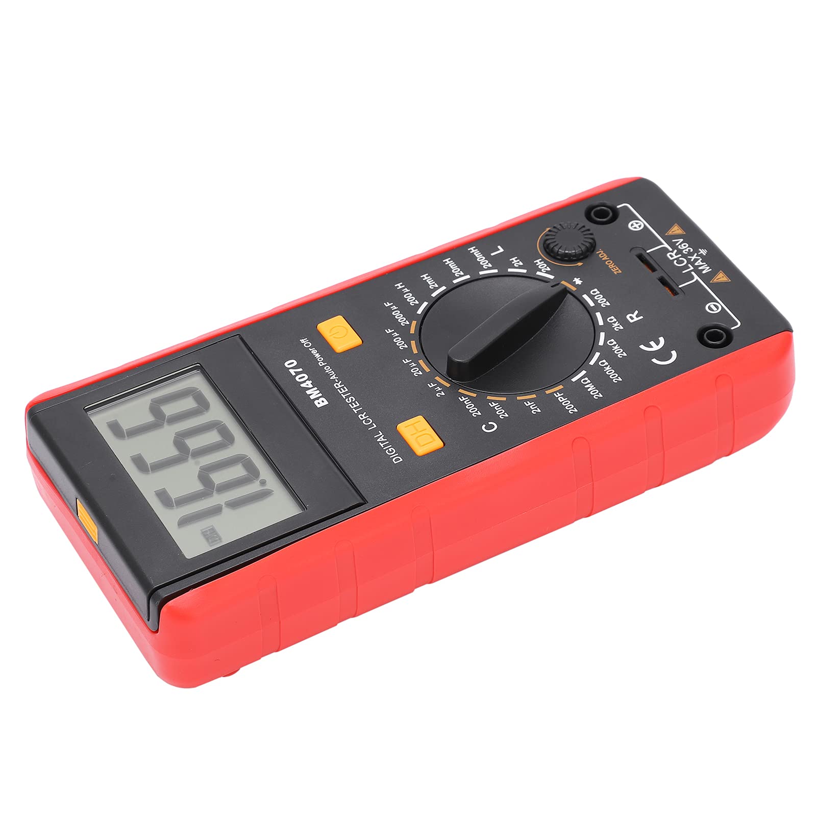
Figure 1 : Face avant view of the Generic BM4070 LCD Digital Multimeter, showing the LCD display, rotary switch, and function buttons.

Figure 2: Close-up of the BM4070's high-definition LCD display, showing a clear numerical reading.
Composants clés :
- Écran LCD : Affiche les mesures et les indicateurs.
- Commutateur rotatif : Used to select measurement functions (Capacitance C, Inductance L, Resistance R) and ranges.
- DH Button: Data Hold function to freeze the current reading on the display.
- Bouton d'alimentation : Allume ou éteint l'appareil.
- Prises d'entrée : Connectez les cordons de test pour effectuer les mesures.
- ZERO ADJ. Knob: For zero adjustment, typically used for resistance measurements to compensate for lead resistance.

Figure 3: Bottom section of the multimeter showing the input jacks and the LCR MAX 36V safety marking.
4. Installation
4.1 Installation de la batterie
- Localisez le compartiment à piles à l'arrière du multimètre.
- Using a screwdriver, carefully open the battery cover.
- Insert one 9V 6F22 battery, ensuring correct polarity. (Battery not included)
- Replacez le couvercle de la batterie et fixez-le avec la vis.
4.2 Connexion des cordons de test
- Assurez-vous que le multimètre est hors tension.
- Insérez le fil de test noir dans la prise d'entrée commune (COM).
- Insert the red test lead into the appropriate input jack for your measurement (e.g., for LCR measurements, use the designated LCR input).
5. Mode d'emploi
5.1 Mise sous/hors tension
Appuyez sur le Bouton d'alimentation (usually marked with a circle and a vertical line) to turn the multimeter on. Press it again to turn the device off.
5.2 Sélection de la fonction de mesure
Faites pivoter le centre Rotary Switch to select the desired measurement function (C for Capacitance, L for Inductance, R for Resistance) and the appropriate range. Start with a higher range if the value is unknown to prevent overloading.
5.3 Réalisation des mesures
- After selecting the function and range, connect the test leads to the component you wish to measure.
- For resistance measurements, you may need to use the ZERO ADJ. knob to zero out the resistance of the test leads before connecting to the component.
- Lire la valeur de mesure affichée sur l'écran LCD.
5.4 Fonction de maintien des données
Appuyez sur le DH Button to freeze the current reading on the display. Press it again to release the hold function and resume live readings.
6. Entretien
- Gardez le multimètre propre et sec. Utilisez un chiffon doux et sec.amp Chiffon de nettoyage ; ne pas utiliser de nettoyants abrasifs ni de solvants.
- Conservez l'appareil dans un endroit frais et sec, à l'abri de la lumière directe du soleil et des températures extrêmes.
- Si l'appareil n'est pas utilisé pendant une période prolongée, retirez la batterie pour éviter les fuites.
- Regularly check the test leads for any signs of wear or damage. Replace them if necessary.
7. Dépannage
If you encounter issues with your BM4070 multimeter, refer to the following common problems and solutions:
- L'appareil ne s'allume pas : Vérifiez que la batterie est correctement installée et suffisamment chargée. Remplacez-la si nécessaire.
- Aucune lecture ni « OL » affiché : Ensure the test leads are properly connected to the component and the correct measurement function and range are selected. 'OL' (Overload) indicates the measured value exceeds the selected range; switch to a higher range.
- Lectures inexactes : Check for proper test lead connection. Ensure the ZERO ADJ. knob is correctly set for resistance measurements. Verify the component is functioning correctly.
Si le problème persiste, contactez le service client.
8. Spécifications
| Fonctionnalité | Spécification |
|---|---|
| Type d'article | Multimètre |
| Modèle | BM4070 |
| Matériel | ABS |
| Alimentation électrique | 1x9V 6F22 Battery (not included) |
| SampTaux de ling | 3 fois par seconde |
| Environnement d'exploitation | 0℃ à 40℃ |
| Environnement de stockage | -10℃ à 50℃ |
| Précision de mesure | 0.1mm (General) |
| Gamme de capacité | 200pF ~ 200μF (±2.5%+5), 2000μF (±5.0%+5) |
| Plage d'inductance | 200uH (±3.0%+5), 2mH ~ 2H (±2%+5), 20H (±5%+5) |
| Vol faibletagAffichage | Battery symbol indication |
9. Contenu du colis
Les éléments suivants sont inclus dans votre colis :

Figure 4: Contents of the BM4070 package, including the multimeter, test clips, manual, and tool bag.
- Multimeter x 1 (Battery not included)
- Test Clips x 2
- Manuel d'instructions x 1
- Sac à outils x 1
10. Garantie et assistance
Specific warranty and support information is not provided in the product details. Please refer to the retailer or manufacturer's website for details regarding warranty coverage and customer support options.

