
1. Introduction
This instruction manual provides detailed information on the installation, operation, and maintenance of your QIACHIP DC 12V 24V 4-Channel 10A Wireless RF Remote Control Relay Receiver. Please read this manual thoroughly before use to ensure proper functionality and safety.
The QIACHIP wireless remote control relay receiver is designed to provide convenient control over various electrical devices such as lighting systems, garage doors, and motors. It operates on a 433MHz frequency and comes with two RF transmitters for flexible control.
2. Consignes de sécurité
- Assurez-vous que l'alimentation électrique est débranchée avant toute opération de câblage ou de maintenance.
- This device operates with DC 12V or 24V. Verify your power source matches the device's requirements.
- Do not exceed the maximum current rating of 10A per channel.
- L'installation doit être effectuée par un personnel qualifié si vous avez des doutes concernant le câblage électrique.
- Gardez l’appareil à l’abri de l’eau et des températures extrêmes.
3. Produit terminéview
The QIACHIP wireless relay receiver system consists of a receiver board and two remote control transmitters.

Figure 3.1: Receiver Board Components. This image shows the QIACHIP KR1204B receiver board with key components labeled, including the antenna, indicator light, learning button, NO (Normally Open), COM (Common), NC (Normally Closed) terminals for relays, and power supply terminals (+V, -V).

Figure 3.2: Detailed Receiver Board. A closer look at the receiver board, highlighting the antenna, indicator, learning button, relays, and terminal blocks for NO, COM, NC connections, and power input.
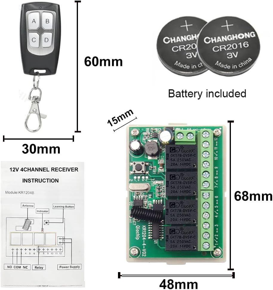
Figure 3.3: Remote Control and Batteries. This image displays the compact 4-button remote control transmitter and the CR2016/CR2032 button cell batteries required for its operation.
4. Spécifications
| Fonctionnalité | Spécification |
|---|---|
| Numéro de modèle | KR1204B |
| Vol d'entrée/sortietage (Relay Contacts) | 1 V à 250 V |
| Vol de travailtage (Récepteur) | DC 6V~30V (Typically 12V/24V) |
| Courant nominal | 10 Ampere (per relay) |
| Type de contact | Normalement ouvert (NO), commun (COM), normalement fermé (NC) |
| Matériau de contact | Alliage d'argent |
| Fréquence sans fil | 433 MHz |
| Portée de la télécommande | Jusqu'à 40 mètres (sans obstacles) |
| Dimensions | 6 x 4 x 2 cm (Receiver board) |
| Poids | 120 g |
| Batterie de l'émetteur | 1 pile CR2032 (incluse) |
5. Configuration et câblage
The receiver board has terminals for power input and relay outputs. Ensure correct polarity for DC power. The relays provide Normally Open (NO), Common (COM), and Normally Closed (NC) contacts for flexible wiring with various devices.
5.1 Connexion d'alimentation
Connect your DC 12V or 24V power supply to the +V and -V terminals on the receiver board. Observe correct polarity.
5.2 Device Wiring Examples
The following diagrams illustrate common wiring configurations for different applications. Always ensure the power to the device being controlled is off before making connections.

Figure 5.1 : Schémas de câblage typiques. This image shows various wiring configurations for the 4-channel relay receiver, including connections for multiple lamps, a curtain motor, and a garage motor. Note the separate power inputs for the receiver (DC 5V-30V) and the controlled devices (1V-250V).
- Pour les lumières : Connect the light's power line through the NO and COM terminals of a relay. When the relay is activated, the circuit closes, and the light turns on.
- For Motors (e.g., Curtain or Garage Door): Motors often require polarity reversal for direction control. Use two relays for this, connecting one for forward and one for reverse, or use a specific motor control module if available. Refer to the diagram for specific motor wiring.
6. Modes de fonctionnement et programmation
The receiver supports three operating modes: Momentary, Toggle, and Latched. You can program each channel independently.
6.1 Clearing Existing Codes (Reset)
Before programming a new mode or remote, it is recommended to clear any previously learned codes.
- Press the "Learning Button" on the receiver board 8 times.
- The indicator light will flash several times, then turn off, indicating that all stored codes have been cleared.

Figure 6.1: Clear Code Function. This diagram illustrates the process of clearing all learned remote control codes from the receiver by pressing the learning button 8 times.
6.2 Programmation des modes de fonctionnement
6.2.1 Mode momentané (mode jogging)
In Momentary Mode, the relay remains active only while the remote button is pressed. ReleasinLe bouton g désactive le relais.
- Press the "Learning Button" on the receiver board once. The indicator light will turn on.
- Press the desired button on your remote control (e.g., button A). The indicator light will flash and then turn off, confirming successful programming.

Figure 6.2: Momentary Mode Programming. This image details the steps to set the receiver to Momentary Mode, where the relay is active only while the remote button is held down.
6.2.2 Toggle Mode (Self-Locking Mode)
In Toggle Mode, pressing the remote button once activates the relay, and it remains active until the same button is pressed again to deactivate it.
- Press the "Learning Button" on the receiver board twice. The indicator light will turn on.
- Press the desired button on your remote control (e.g., button A). The indicator light will flash and then turn off, confirming successful programming.

Figure 6.3: Toggle Mode Programming. This image illustrates the procedure for programming the receiver into Toggle Mode, where a single button press switches the relay state (on/off).
6.2.3 Latched Mode (Interlock Mode)
In Latched Mode, pressing one button on the remote activates its corresponding relay and simultaneously deactivates any other active relays on the board. This is useful for applications where only one output should be active at a time (e.g., motor direction control).
- Press the "Learning Button" on the receiver board three times. The indicator light will turn on.
- Press the desired button on your remote control (e.g., button A). The indicator light will flash and then turn off, confirming successful programming.

Figure 6.4: Latched Mode Programming. This image demonstrates how to program the receiver for Latched Mode, where activating one relay automatically deactivates others, suitable for interlocked operations.
7. Entretien
7.1 Remplacement de la pile de la télécommande
The remote control uses a CR2032 button cell battery. If the remote's range decreases or it stops responding, replace the battery:
- Ouvrez soigneusement le boîtier de la télécommandeasing.
- Retirez l'ancienne pile CR2032.
- Insérez une nouvelle pile CR2032 en veillant à respecter la polarité (+ côté vers le haut).
- Fermez la télécommande casing en toute sécurité.
7.2 Entretien général
- Gardez le récepteur et les télécommandes propres et secs.
- Évitez d'exposer les appareils à la lumière directe du soleil ou à des températures extrêmes.
- Do not attempt to repair the device yourself if you are not qualified. Contact support for assistance.
8. Dépannage
| Problème | Cause possible | Solution |
|---|---|---|
| Le récepteur ne répond pas à la télécommande. |
|
|
| Device connected to relay does not turn on/off. |
|
|
| Interférences avec d'autres appareils RF. | Operating on 433MHz frequency. | Relocate the receiver or other RF devices to minimize interference. |
9. Garantie et assistance
QIACHIP products are designed for reliability and performance. This product comes with a standard manufacturer's warranty against defects in materials and workmanship. Please refer to your purchase documentation for specific warranty terms and duration.
For technical support, troubleshooting assistance, or warranty claims, please contact your retailer or the QIACHIP customer service team. Contact information can typically be found on the product packaging or the official QIACHIP website.
When contacting support, please have your product model number (KR1204B+2KT06) and purchase date available.