
1. Introduction
This manual provides detailed instructions for the safe and efficient operation of your DeWin DC 24V Digital Display Timer Delay Cycle Relay Module. Please read this manual thoroughly before installation and use, and keep it for future reference.
The module is designed for precise timing control in various applications, featuring a digital display for easy parameter setting and monitoring. It offers low power consumption and is built with high-quality, durable materials.
2. Consignes de sécurité
Avertissement: Electrical components can be dangerous. Always ensure power is disconnected before installation or maintenance. Professional installation is highly recommended to prevent electrical shock or damage to the device.
- Do not operate the module beyond its specified voltaget (CC 24V).
- Assurez-vous que tous les branchements électriques sont bien fixés et corrects conformément au schéma de câblage.
- Keep the module away from moisture, extreme temperatures, and corrosive environments.
- Do not attempt to modify or disassemble the module, as this may void the warranty and pose safety risks.
3. Produit terminéview
The DeWin DC 24V Digital Display Timer Delay Cycle Relay Module is a compact and portable control board designed for various timing applications. It features a clear digital display and intuitive buttons for setting operational parameters.
3.1 Principales caractéristiques
- Digital display for precise time and parameter visualization.
- Three adjustable parameter sets: P0 (timing range), P1 (working mode), P2 (display brightness).
- Construction durable avec des matériaux de haute qualité.
- Faible consommation d'énergie.
- Compact size: 7.1 x 3.9 x 2.5 cm.
3.2 Identification des composants
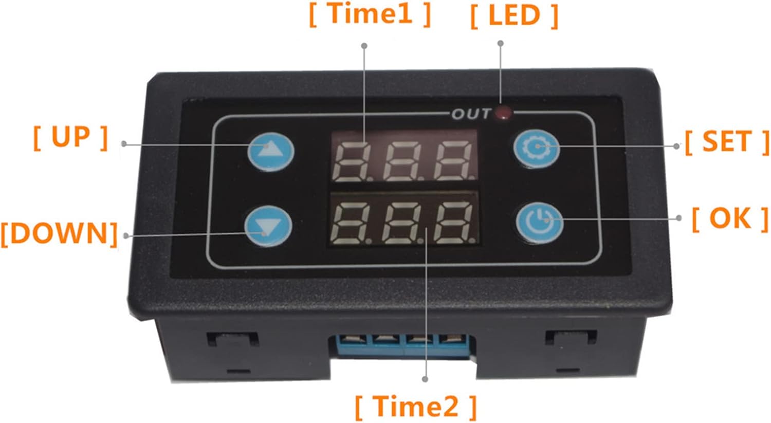
This image shows the front panel of the DeWin timer relay module. Key components are labeled: "UP" button (top left), "DOWN" button (bottom left), "SET" button (top right), "OK" button (bottom right), "Time1" display (top center), "Time2" display (bottom center), and an "OUT" LED indicator light.
- Digital Displays (Time1, Time2): Show current time values or parameter settings.
- Bouton HAUT : Utilisé pour augmenter des valeurs ou naviguer dans les menus.
- Bouton BAS : Utilisé pour diminuer des valeurs ou naviguer dans les menus.
- Bouton de réglage: Passe en mode de paramétrage.
- Bouton OK : Confirms settings and restarts the timer.
- DEL DE SORTIE : Indicates relay output status.
4. Spécifications
| Paramètre | Valeur |
|---|---|
| Vol d'exploitationtage | 24 volts CC |
| Marque | DeWin |
| Matériel | Acrylonitrile butadiène styrène |
| Dimensions de l'article (L x l x H) | 7.1 x 3.9 x 2.5 centimètres |
| Modèle | DEWINvbhaozkn3s |
| Pays d'origine | Chine |
5. Configuration et câblage
Before connecting the module, ensure the power supply is disconnected. Refer to the wiring diagram below for correct connections.

This diagram illustrates how to connect the DeWin timer relay module. It shows connections for a DC/AC power source (Red + and Black -) and a load (e.g., a fan) connected to the module's output terminals. Ensure positive and negative terminals are correctly matched.
- Connect the DC 24V power supply to the designated input terminals (usually marked + and -).
- Connect your load (e.g., motor, light) to the output terminals of the relay. Ensure the load's power requirements are within the relay's specifications.
- Vérifiez minutieusement la polarité et la sécurité de toutes les connexions avant de mettre l'alimentation sous tension.
6. Mode d'emploi
The module features three main parameter sets (P0, P1, P2) for configuration. Use the SET, UP, DOWN, and OK buttons to navigate and adjust settings.

This image displays the three main parameter settings for the DeWin Delay Relay Module: P0 for timing range, P1 for working mode, and P2 for display brightness adjustment.
6.1 Setting Parameters (P0, P1, P2)
- Entrez dans le mode de réglage : Appuyez et maintenez enfoncé le ENSEMBLE button until the display changes to show parameter options (e.g., P0).
- Sélectionner un paramètre : Utilisez le UP or VERS LE BAS buttons to cycle through P0, P1, P2.
- Ajuster la valeur du paramètre : Once the desired parameter (e.g., P0) is displayed, press the ENSEMBLE button again to enter its value adjustment mode. Use UP or VERS LE BAS pour changer la valeur.
- Confirm and Save: After setting the value, press the OK button to save the setting and return to the parameter selection menu. Repeat for P1 and P2 as needed.
- Quitter le mode de réglage : Appuyez et maintenez enfoncé le ENSEMBLE button again to exit the setting mode and return to normal operation.
6.2 OK Button Functions
Le OK button serves two primary functions:
- Save and Start: After setting parameters, pressing the OK button saves the configuration and initiates the timer's operation.
- Restart Timer: If the timer has completed its cycle and you wish to restart it, a short press of the OK button will re-trigger the function and restart the timer.
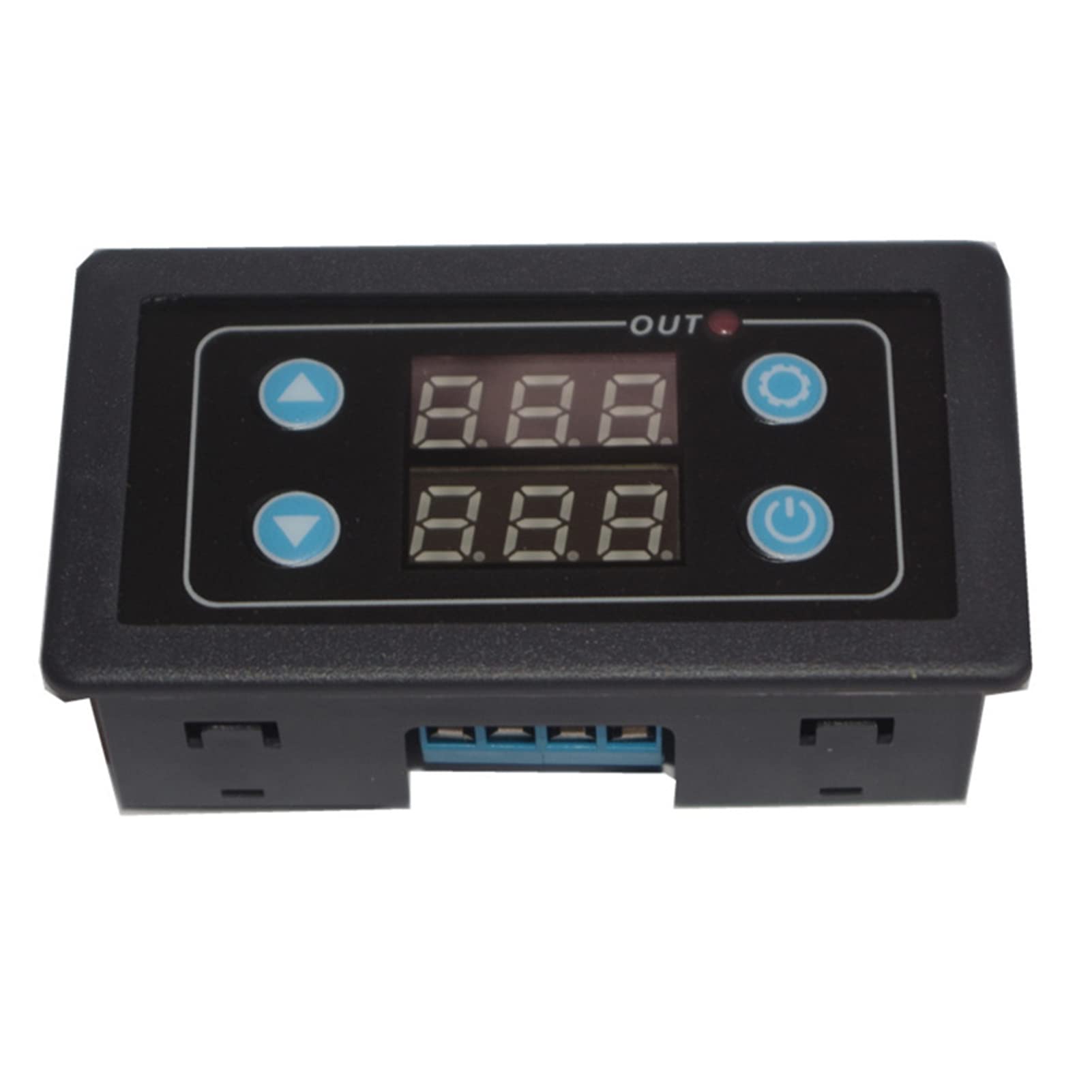
This image shows two DeWin timer relay modules. The text overlay explains: "Trigger the function again. After the timer has finished working normally, it needs to work again. Short press the confirm button to restart the timer."
7. Entretien
- Nettoyage: Utilisez un chiffon doux et sec pour nettoyer le module. N’utilisez pas de nettoyants abrasifs ni de solvants.
- Inspection: Periodically check wiring connections for looseness or signs of wear.
- Stockage: If storing the module for an extended period, keep it in a dry, dust-free environment.
8. Dépannage
| Problème | Cause possible | Solution |
|---|---|---|
| Le module ne s'allume pas. | Incorrect power connection, no power supply, faulty module. | Vérifiez le vol d'alimentationtage (DC 24V). Verify power wiring polarity and connections. If issues persist, the module may be faulty. |
| Le relais ne s'active pas. | Incorrect parameter settings, faulty wiring to load, load exceeding relay capacity. | Review P0 and P1 settings. Check wiring to the load. Ensure the load's current/voltage is within the relay's limits. |
| L'écran est sombre ou illisible. | P2 (display brightness) setting is too low. | Adjust P2 parameter to increase display brightness. |
Si vous rencontrez des problèmes non répertoriés ici ou si les solutions proposées ne résolvent pas le problème, veuillez contacter le service client.
9. Garantie et assistance
This product comes with a standard manufacturer's warranty. Please refer to your purchase documentation for specific warranty terms and duration. For technical support, troubleshooting assistance, or warranty claims, please contact your retailer or the manufacturer directly.
Manufacturer: DEWIN
Model: DEWINvbhaozkn3s