1. Introduction
This manual provides detailed instructions for the installation, operation, and maintenance of the Huanyang 1.5KW 2HP Variable Frequency Drive (VFD) Inverter. This VFD is designed for precise motor speed control in various applications, including lathes, mills, car hoists, pumps, and conveyors. It supports both single-phase and three-phase input, providing a three-phase output for motor control. The VFD utilizes Sine Wave Pulse Width Modulation (SPWM) for its control system, ensuring excellent performance and efficiency.
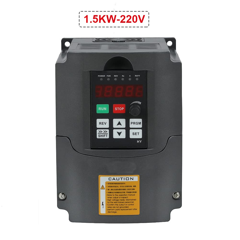
Figure 1: Huanyang 1.5KW 2HP Variable Frequency Drive Inverter.
2. Consignes de sécurité
AVERTISSEMENT: Improper installation or operation can lead to serious injury or death. Read this manual thoroughly before installation and operation. Only qualified personnel should install, operate, and maintain this equipment.
- Always disconnect power before performing any wiring, inspection, or maintenance.
- Assurez-vous d'une mise à la terre correcte du variateur de fréquence et du moteur.
- Do not touch electrical components when power is applied. High voltage is present even after power is disconnected; wait for capacitors to discharge.
- Vérifier le volume d'entréetage matches the VFD's specifications (220V).
- Install the VFD in a clean, dry, and well-ventilated environment, away from direct sunlight, corrosive gases, and excessive vibration.
- Utilisez des calibres de fil appropriés pour les connexions électriques afin d'éviter la surchauffe.
- Assurez-vous que toutes les connexions sont sécurisées et correctement isolées.
- Refer to local electrical codes and regulations for installation requirements.
3. Produit terminéview
3.1 Principales caractéristiques
- Phase d'entrée: Supports 1-phase or 3-phase 220V input.
- Phase de sortie : 3-phase 220V output.
- Système de contrôle: Sine Wave PWM (SPWM) for precise motor control.
- PLC Function: Easy PLC function for 16-segment speed and inverter control.
- Fonctionnement silencieux : Carrier frequency adjustable up to 16KHz for soundless working.
- Anti-jamming Capability: Extremely strong anti-jamming performance.
- Low Speed Torque: 0.5Hz-150% low output rated torque.
- AVR Technique: Vol automatiquetage Regulation (AVR) ensures stable load capability.
- Error Protection: Perfect error protection and short circuit starting protection.
- Communication: RS485 communication port with standard international MODBUS protocol.
3.2 Composants et interface

Figure 2: Front panel with display and control buttons, showing internal access.
The VFD features a user-friendly control panel with a digital display and various buttons for operation and parameter setting. The main control buttons include RUN, STOP, REV (Reverse), SHIFT, UP, DOWN, PRGM (Program), and SET.

Figure 3 : Détaillé view of the VFD's terminal block for power and control wiring.
The terminal block provides connections for input power (R, S, T for 3-phase or L1, L2 for single-phase), output to the motor (U, V, W), and various control signals. This model is equipped with two rows of terminals for comprehensive control options.
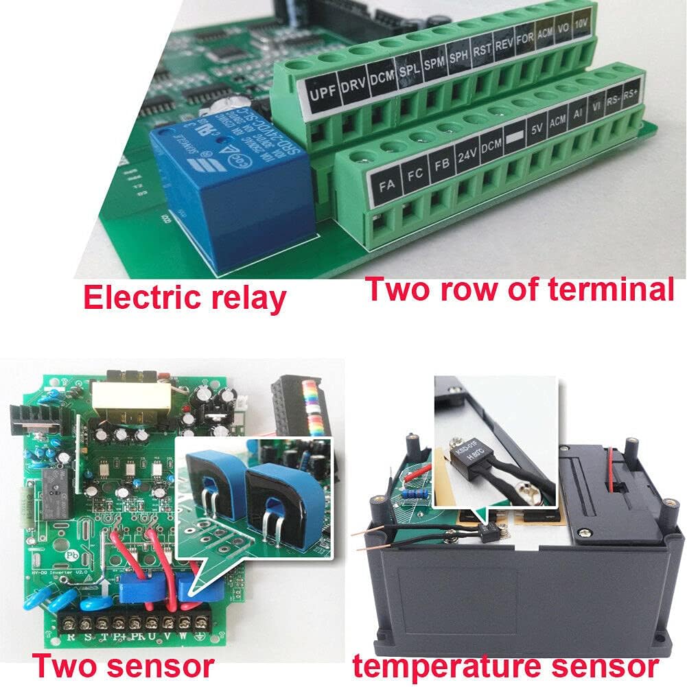
Figure 4 : Interne view highlighting the electric relay and two sensors, contributing to enhanced functionality and protection.
Internally, the VFD incorporates robust components such as an electric relay and two sensors, which contribute to its reliable operation and protective features. It also features bigger capacitors and transformers for improved performance and stability compared to some other models.
4. Spécifications
| Fonctionnalité | Valeur |
|---|---|
| Numéro de modèle | USTS15220V-D-AMZ |
| Puissance nominale | 1.5KW (2HP) |
| Vol d'entréetage | 220 Volts (Single or 3 Phase) |
| Volume de sortietage | 220 Volts (3 Phase) |
| Évaluation actuelle | 7A |
| Méthode de contrôle | Sine Wave PWM (SPWM) |
| Port de communication | RS485 (MODBUS) |
| Fréquence porteuse | Adjustable up to 16KHz |
| Poids de l'article | 3.99 livres |
| Dimensions du colis | 9.5 x 9.4 x 7.6 pouces |
| Couleur | Noir |

Figure 5: Approximate dimensions of the VFD unit.
5. Configuration et installation
5.1 Montage
Mount the VFD vertically on a stable, non-flammable surface in an area with adequate ventilation. Ensure sufficient clearance around the unit for heat dissipation. Avoid mounting in direct sunlight or areas with excessive dust, moisture, or corrosive substances. Use appropriate fasteners to secure the unit firmly.

Figure 6 : Côté view of the VFD, showing ventilation grilles for proper airflow.
5.2 Connexions de câblage
All wiring must be performed by a qualified electrician in accordance with local and national electrical codes. Ensure power is disconnected before making any connections.
- Puissance d'entrée (220 V) : Connect the incoming AC power to the input terminals (R, S, T for 3-phase or L1, L2 for single-phase). This VFD supports both single-phase and three-phase 220V input.
- Sortie du moteur: Connect the three-phase motor leads to the output terminals (U, V, W). Ensure correct phase sequence for desired motor rotation.
- Mise à la terre : Connect the ground terminal of the VFD to a reliable earth ground. The motor frame must also be properly grounded.
- Terminaux de contrôle : Utilize the control terminals for external control signals such as start/stop commands, speed reference (e.g., potentiometer, 0-10V, 4-20mA), and fault indications. Refer to the detailed wiring diagram in the full product manual for specific terminal assignments.
- Communication RS485: If using MODBUS communication, connect the RS485 A and B lines to the designated terminals.
Note: Always refer to the wiring diagram provided with your specific VFD unit for precise terminal identification and connection instructions.
6. Mode d'emploi
6.1 Fonctionnement de base
- Mise sous tension : After ensuring all connections are secure and safe, apply power to the VFD. The digital display will illuminate.
- Démarrer le moteur : Appuyez sur le COURIR button on the control panel to start the motor.
- Arrêter le moteur : Appuyez sur le ARRÊT bouton pour arrêter le moteur.
- Sens inverse : Appuyez sur le TOUR button to change the motor's rotation direction.
Contrôle de vitesse 6.2
Motor speed can be controlled via the built-in potentiometer, external analog signals (e.g., 0-10V, 4-20mA), or digital inputs, depending on parameter settings.
- Potentiomètre: Rotate the potentiometer knob on the control panel to adjust the output frequency and thus the motor speed.
- External Analog Input: If configured, an external voltage or current signal connected to the AI terminals can control the speed.
- Entrées numériques: Pre-set speeds can be selected using digital input terminals, often used with the PLC function.
6.3 Réglages des paramètres
The VFD has numerous parameters that can be adjusted to customize its operation for specific applications. These parameters control motor characteristics, acceleration/deceleration times, control modes, and protective functions.
- Entrez en mode programme : Appuyez sur le PRGM button to enter the parameter setting mode.
- Paramètres de navigation : Utilisez le UP et VERS LE BAS arrow buttons to scroll through parameter groups and individual parameters.
- Sélectionner un paramètre : Presse ENSEMBLE pour sélectionner un paramètre à modifier.
- Ajuster la valeur : Utilisez le UP et VERS LE BAS buttons to change the parameter value. The CHANGEMENT button can be used to move the cursor for digit selection.
- Enregistrer la valeur : Presse ENSEMBLE à nouveau pour enregistrer la nouvelle valeur.
- Quitter le mode programme : Presse PRGM to exit the parameter setting mode and return to the main display.
Consult the comprehensive parameter list in the full product manual for detailed descriptions and recommended settings for each parameter.
6.4 fonctions avancées
- PLC Function: The VFD includes an easy PLC function that allows for programming up to 16 segments of speed and inverter control, enabling complex automated sequences without an external PLC.
- Communication RS485: The built-in RS485 port supports the standard MODBUS protocol, allowing the VFD to be integrated into a larger control system for remote monitoring and control.
7. Entretien
Regular maintenance ensures the longevity and reliable operation of your VFD. Always disconnect power and wait for capacitors to discharge before performing any maintenance.
- Nettoyage: Nettoyez régulièrement l'extérieur et les ouvertures de ventilation du variateur de fréquence afin d'éviter l'accumulation de poussière, qui peut entraver le refroidissement. Utilisez un chiffon doux et sec. N'utilisez pas de nettoyants liquides.
- Inspection: Vérifiez régulièrement le serrage des connexions électriques et recherchez des signes d'usure ou de dommages. Soyez attentif à tout bruit ou odeur inhabituel pendant le fonctionnement.
- Contrôle environnemental : Ensure the operating environment remains within specified temperature and humidity ranges and is free from excessive dust or corrosive elements.
- Vérification du ventilateur : Vérifiez que le ventilateur de refroidissement fonctionne librement et n'est pas obstrué.
8. Dépannage
This section provides general guidance for common issues. For detailed error codes and advanced troubleshooting, refer to the complete product manual.
| Problème | Cause possible | Solution |
|---|---|---|
| Le variateur de fréquence ne s'allume pas. | Absence d'alimentation ; fusible grillé ; erreur de câblage | Check power supply; Inspect fuses; Verify input wiring. |
| Le moteur ne fonctionne pas | STOP button pressed; Fault condition; Incorrect parameters; Motor wiring error | Press RUN; Check display for fault codes and clear; Verify motor parameters and wiring. |
| Motor runs at incorrect speed | Incorrect speed reference; Parameter settings incorrect | Adjust potentiometer or external signal; Check frequency and motor parameters. |
| Défaut de surintensité | Motor overload; Short circuit in motor wiring; Rapid acceleration/deceleration | Reduce load; Check motor wiring; Increase acceleration/deceleration times. |
| Survoltage/Undervoltage défaut | Unstable input power; Regenerative braking | Vérifier le volume d'entréetage stability; Consider braking resistor if regenerative braking is an issue. |
9. Garantie et assistance
For specific warranty terms, conditions, and technical support, please refer to the documentation provided at the time of purchase or contact the manufacturer, Huanyang, directly. Warranty coverage typically includes defects in materials and workmanship under normal use. Keep your purchase receipt as proof of purchase.
Contact information for support can usually be found on the product packaging, the manufacturer's official websur le site, ou auprès de votre revendeur agréé.