Docooler XUH6362338938855GM
Docooler JINGSHA X99-8D3 Motherboard User Manual
Model: XUH6362338938855GM
1. Introduction et plusview
The Docooler JINGSHA X99-8D3 is a high-performance ATX gaming motherboard designed for LGA2011 V3 processors. It features four-channel DDR3 memory support, an M.2 NVME slot for high-speed storage, and multiple PCI-E expansion slots, making it suitable for demanding computing tasks and gaming setups. This manual will guide you through the installation, configuration, and maintenance of your motherboard.
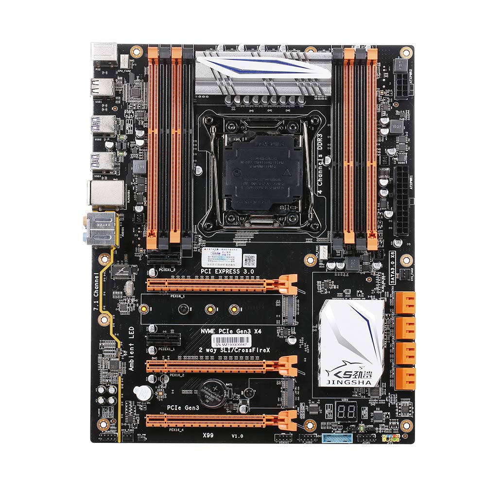
Figure 1.1 : Vue de dessus view of the Docooler JINGSHA X99-8D3 Motherboard, showcasing its layout with CPU socket, RAM slots, and various expansion slots.
2. Principales caractéristiques
- M.2 NVME Support: Equipped with an M.2 hard disk port, supporting high-speed PCI-E NVME X4 for optimal operating system and application driver performance.
- Quad-Channel DDR3 Memory: Features 8 DDR3 memory slots across 4 channels, significantly improving capacity and performance, supporting up to 256GB.
- Digital Diagnostic Card: Integrated digital diagnostic card automatically tests hardware devices to ensure proper operation and assist in troubleshooting.
- Multiple PCI-E Expansion Slots: Provides 3 PCI-E expanded slots, configurable as X16/X8 to handle various workloads and multi-GPU setups.
- Construction durable : Built with a 10-layer PCB and high-quality capacitors for enhanced stability and heat resistance.

Figure 2.1: Diagram illustrating the six core technologies and features of the motherboard, including 4-channel DDR3*8, M.2 hard disk interface, digital diagnostic card, 7.1 channel audio, SATA3.0*8 interface, and Crossfire support.
3. Contenu du colis
Veuillez vérifier que tous les articles énumérés ci-dessous sont présents dans votre colis :
- 1x Docooler JINGSHA X99-8D3 Motherboard
- 1x câble SATA
- 1x I/O Baffle (Backplate)
- 1x CPU Fan Board
- A bag of screws
4. Spécifications
| Fonctionnalité | Spécification |
|---|---|
| Modèle | X99-8D3 |
| Facteur de forme | ATX |
| Graphic Slot | PCIE3.0 16X*3 |
| Carte réseau | Carte réseau Gigabit |
| Canal audio | Canal 7.1 |
| CPU Type Support | LGA2011 V3 (2629V3/2649V3/2669V3/2678V3/2696V3/2676V3/2673V3) |
| Couches PCB | 10 couches |
| slot mémoire | DDR3*8 |
| Capacité de mémoire maximale | 256 Go |
| Interface SATA | SATA3.0*8, M.2 NVME |
| Interface PS/2 | Souris / clavier |
| Alimentation électrique | 8 PIN*1, 24 PIN*1 |
| Interface USB | USB 3.0*6, USB 2.0*6 |
| Expanded Interface | PCIE 1X*2, M.2 WIFI*1 |
| Taille de l'article | 30.2 x 24.4 cm (11.89 x 9.61 pouces) |
| Poids de l'article | 930.5 g (32.82 oz) |

Figure 4.1 : Détaillé view of the motherboard's rear I/O panel, showing PS/2 ports, USB 2.0, USB 3.0, Gigabit Network Port, and 7.1 Audio Ports.
5. Configuration et installation
Avant de commencer l'installation, assurez-vous que votre système est éteint et débranché de la prise murale. Manipulez la carte mère par ses bords pour éviter les décharges électrostatiques.
5.1 Installation du processeur
- Locate the LGA2011 V3 CPU socket on the motherboard.
- Gently push down the CPU retention lever and swing it open.
- Align the triangular mark on your CPU with the corresponding mark on the socket. Carefully place the CPU into the socket without forcing it.
- Fermez le levier de retenue pour fixer le processeur.
- Appliquez une fine couche uniforme de pâte thermique sur le dessus du processeur.
- Installez le refroidisseur de processeur conformément aux instructions du fabricant, en veillant à un contact et une pression corrects.

Figure 5.1 : Gros plan view of the LGA2011 V3 CPU socket on the motherboard, ready for CPU installation.
5.2 Installing RAM Modules
- Ouvrez les clips situés aux deux extrémités des emplacements de mémoire DDR3.
- Alignez l'encoche du module de RAM avec le détrompeur dans l'emplacement mémoire.
- Appuyez fermement sur les deux extrémités du module de RAM jusqu'à ce que les clips s'enclenchent, fixant ainsi le module.
- For optimal performance, install RAM modules in matching pairs across the four channels as indicated in the motherboard manual or silkscreen.

Figure 5.2 : View of the eight DDR3 RAM slots on the motherboard, showing their arrangement for quad-channel memory configuration.
5.3 Installing Storage Devices (M.2 NVME & SATA)
- M.2 NVME SSD: Locate the M.2 slot. Insert the M.2 SSD at an angle into the slot, then gently push it down and secure it with the provided screw.
- Disques SATA : Connect your SATA SSDs or HDDs to the SATA 3.0 ports using SATA data cables. Ensure the power supply SATA power connectors are also attached to the drives.

Figure 5.3: Close-up of the M.2 interface on the motherboard, highlighting its position and the PCI-E Gen3 X4 connection for high-speed data transfer.
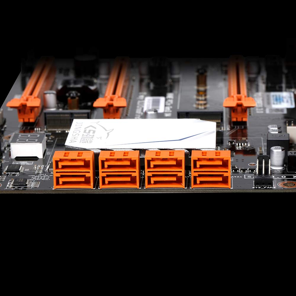
Figure 5.4 : View of the eight orange SATA 3.0 ports on the motherboard, providing ample connectivity for storage devices.
5.4 Connexion de l'alimentation
- Connect the 24-pin ATX power connector from your power supply unit (PSU) to the corresponding port on the motherboard.
- Connect the 8-pin CPU power connector (EPS12V) from your PSU to the 8-pin port near the CPU socket.
5.5 Installation des cartes d'extension (PCIe)
- Locate the desired PCI-E 3.0 x16 or x1 slots.
- Retirez le cache de l'emplacement d'extension correspondant de votre boîtier PC.
- Align the expansion card with the slot and press down firmly until it is fully seated. Secure the card with a screw to the case.

Figure 5.5 : Angulaire view of the motherboard, highlighting the three PCI Express 3.0 x16 slots and the smaller PCIe x1 slots, ready for graphics cards and other expansion cards.
6. Utilisation de la carte mère
6.1 Premier démarrage et configuration du BIOS
- Une fois tous les composants assemblés, branchez votre moniteur, votre clavier et votre souris.
- Mettez votre système sous tension. Pendant la séquence de démarrage initiale, appuyez plusieurs fois sur la touche DEL or F2 key (common for JINGSHA motherboards) to enter the BIOS/UEFI setup utility.
- Dans le BIOS, vérifiez que tous les composants installés (processeur, RAM, stockage) sont correctement détectés.
- Configurez l'ordre de démarrage pour donner la priorité à votre support d'installation du système d'exploitation (clé USB ou DVD).
- Enregistrez les modifications et quittez le BIOS. Le système redémarrera.
6.2 Installation du système d'exploitation
Follow the instructions provided with your operating system (e.g., Windows, Linux) to complete the installation process. Ensure you install all necessary drivers for the motherboard's chipsets, network, audio, and other components from the manufacturer's website ou disque de pilote inclus.
7. Entretien
Un entretien approprié garantit la longévité et le fonctionnement stable de votre carte mère.
- Élimination de la poussière : Nettoyez régulièrement la poussière de la carte mère et des composants à l'aide d'air comprimé. Assurez-vous que le système est éteint et débranché avant le nettoyage.
- Mises à jour du BIOS : Periodically check the Docooler or JINGSHA official website for BIOS updates. BIOS updates can improve compatibility, stability, and performance. Follow update instructions carefully to avoid damaging the motherboard.
- Mises à jour du pilote: Maintenez vos pilotes système à jour pour garantir des performances optimales et une compatibilité avec les nouveaux logiciels et matériels.
- Conditions environnementales : Utilisez la carte mère dans un environnement bien ventilé, à température et humidité stables, afin d'éviter la surchauffe et la dégradation des composants.
8. Dépannage
Cette section aborde les problèmes courants que vous pourriez rencontrer.
8.1 Pas d'alimentation / Pas de démarrage
- Ensure the 24-pin ATX and 8-pin CPU power connectors are securely plugged into the motherboard.
- Check if the power supply unit (PSU) is switched on and connected to a working power outlet.
- Vérifiez que le câble du bouton d'alimentation du panneau avant est correctement connecté au connecteur de la carte mère.
8.2 Aucun affichage
- Ensure your graphics card (if dedicated) is properly seated in its PCI-E slot and has all necessary power cables connected.
- Check that your monitor cable is securely connected to the graphics card or motherboard (if integrated graphics are used, though X99 typically requires a dedicated GPU).
- Try reseating your RAM modules. Incorrectly seated RAM is a common cause of no display.
8.3 POST Code Display (Digital Diagnostic Card)
The motherboard is equipped with a digital diagnostic card (POST code display) that shows a two-digit code during boot-up. Refer to the motherboard's detailed technical documentation (often available on the manufacturer's website) for a list of POST codes and their meanings. This can help pinpoint the exact component causing a boot failure.

Figure 8.1 : Gros plan view showing the integrated digital diagnostic card (POST code display) on the motherboard, which assists in identifying hardware issues during boot.
9. Garantie et assistance
For warranty information and technical support, please refer to the documentation provided with your purchase or visit the official Docooler or JINGSHA webConsultez le site. Conservez votre preuve d'achat pour toute réclamation au titre de la garantie.
Ask a question about this manual
Ask about setup, troubleshooting, compatibility, parts, safety, or missing instructions. Manuals+ will review the question and use this page’s manual context to help answer it.