Introduction
This manual provides detailed instructions for the installation, operation, and maintenance of the DROK DC 8-36V 5A PWM Motor Speed Controller. This device is designed to precisely control the speed of DC motors and adjust the brightness of LEDs by utilizing Pulse Width Modulation (PWM) technology. It operates within a wide voltage range of 8V to 36V DC and supports a maximum current of 5A.
Configuration et installation
Identification des composants
Familiarize yourself with the key components of the motor speed controller before installation. A typical layout includes:
- Alimentation CC 8-36 V : Terminals for connecting the power supply.
- Motor Wiring Terminals: Terminals for connecting the DC motor. Changing the wiring direction here reverses the motor's rotation.
- Speed Regulator Potentiometer (with switch): Used to adjust the output PWM duty cycle, thereby controlling motor speed or LED brightness. It also functions as an ON/OFF switch.
- Yellow Working Indicator: Illuminates when the module is powered and operating.
- High-quality Power Tube & Schottky Diode: Essential components for power regulation and protection.
- Surface Mount Fuse: Assure une protection contre les surintensités.
- Immersion Gold PCB: High-quality circuit board material.
Note: For a visual reference of component locations, please refer to the product images provided on the product page.

Figure 1 : Haut view of the DROK DC Motor Speed Controller, showing various components and heat sinks.
Instructions de câblage
Follow these steps to correctly wire the motor speed controller:
- Connexion d'alimentation : Connect your DC power supply (8-36V) to the 'DC 8-36V Power Input' terminals. Ensure correct polarity: '+' to positive, '-' to negative.
- Connexion du moteur: Connect your DC motor to the 'Motor Wiring Terminals'. The motor's positive and negative terminals can be connected to either terminal on the controller. To reverse the motor's direction, simply swap the motor's wiring connections.
- LED Dimming (Optional): For LED dimming applications, connect the LED strip or module to the 'Motor Wiring Terminals' in place of a motor, observing correct polarity if specified by the LED manufacturer.
Important: Always ensure the power supply is disconnected before making or changing any wiring connections. Double-check all connections for correct polarity and secure fastening to prevent damage to the module or connected devices.
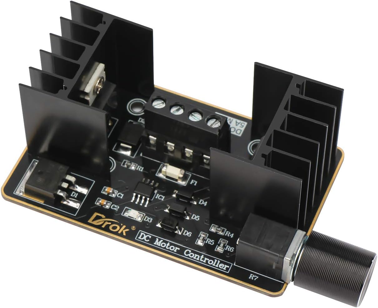
Figure 2 : Gros plan view of the terminal connections on the DROK DC Motor Speed Controller, illustrating where to connect power and motor/LED.
Mode d'emploi
Once the controller is correctly wired and powered on, operate it as follows:
- Marche/Arrêt : The speed regulator potentiometer often includes an integrated switch. Rotate the knob clockwise from the 'OFF' position to power on the module. Continue rotating to increase speed/brightness. Rotate counter-clockwise to decrease speed/brightness and eventually turn off the module.
- Réglage de la vitesse/luminosité : Turn the potentiometer knob clockwise to increase the motor speed or LED brightness. Turn it counter-clockwise to decrease the motor speed or LED brightness. The yellow working indicator will confirm the module is active.
- Direction du moteur: If the motor rotation direction is not as desired, power off the module, swap the two wires connected to the 'Motor Wiring Terminals', and then power on again.

Figure 3 : Gros plan view of the speed regulator potentiometer on the DROK DC Motor Speed Controller, used for power and speed/brightness adjustment.
Entretien
To ensure optimal performance and longevity of your DROK DC Motor Speed Controller, follow these maintenance guidelines:
- Nettoyage: Veillez à ce que le module reste propre et exempt de poussière et de débris. Utilisez un chiffon doux et sec pour le nettoyer. Évitez d'utiliser des liquides ou des nettoyants abrasifs.
- Environnement: Operate the controller in a dry, well-ventilated environment. Avoid exposure to moisture, extreme temperatures, or corrosive substances.
- Dissipation de la chaleur : The module is equipped with heat sinks. Ensure adequate airflow around the module, especially during prolonged operation at higher loads, to prevent overheating. Do not obstruct the heat sinks.
- Relations: Periodically check all wiring connections to ensure they remain secure and free from corrosion. Loose connections can lead to intermittent operation or damage.
Dépannage
| Problème | Cause possible | Solution |
|---|---|---|
| Module has no power / Yellow indicator is off |
|
|
| Motor not spinning / LED not dimming |
|
|
| Motor speed/LED brightness inconsistent |
|
|
Caractéristiques
| Fonctionnalité | Valeur |
|---|---|
| Vol d'exploitationtage | DC 8-36V |
| Courant maximal | 5A |
| Type de contrôle | PWM (modulation de largeur d'impulsion) |
| Poids de l'article | 2.08 onces |
| Dimensions du colis | 5.28 x 2.72 x 1.97 pouces |
| Matériel | Plastique |
| Couleur | Noir |
| ASIN | B086DMNNLR |
| Date de première disponibilité | 5 juin 2020 |
Garantie et assistance
For warranty information or technical support, please refer to the documentation included with your purchase or contact DROK customer service directly. Keep your purchase receipt as proof of purchase for any warranty claims.
For further assistance, visit the official DROK webconsultez le site ou contactez leurs services d'assistance.