1. Introduction
The EPEVER Tracer1210AN MPPT Solar Charge Controller is designed to efficiently manage power from your solar panels to charge batteries. It features advanced Maximum Power Point Tracking (MPPT) technology, ensuring high tracking efficiency of over 99.5%. This controller supports 12V and 24V battery systems automatically and can handle a maximum PV input voltage of 100V. It is compatible with various battery types, including sealed lead-acid, gel, flooded, and lithium batteries. The built-in LCD screen displays key charging parameters, and multiple connectivity options allow for personalized settings and monitoring via remote meter, mobile app, or PC software.
2. caractéristiques du produit
The Tracer1210AN controller integrates several features for optimal performance and user interaction.

- Écran LCD : Shows real-time operating data and fault information.
- Bouton Sélectionner : Used to navigate through different display interfaces.
- Bouton Entrée : Permet de confirmer les sélections ou d'accéder aux menus de paramètres.
- Trous de montage: For secure installation of the controller.
- Port du capteur de température : Connects the Remote Temperature Sensor (RTS) for accurate battery temperature compensation.
- Solar Panel Terminals: Se connecte au champ de panneaux solaires.
- Bornes de batterie : Se connecte au banc de batterie.
- Bornes de chargement : Se connecte aux charges CC.
- COM Port (RS485): For communication with accessories like the MT50 remote meter, PC software, or mobile app.

3. Configuration et installation
Une installation correcte est essentielle au bon fonctionnement et à la sécurité de votre régulateur de charge solaire. Suivez attentivement ces étapes.
3.1 Déballage et composants
Before installation, ensure all components are present and undamaged. The package typically includes the Tracer1210AN controller, an MT50 remote meter, a Remote Temperature Sensor (RTS), and an RS485 PC communication cable.
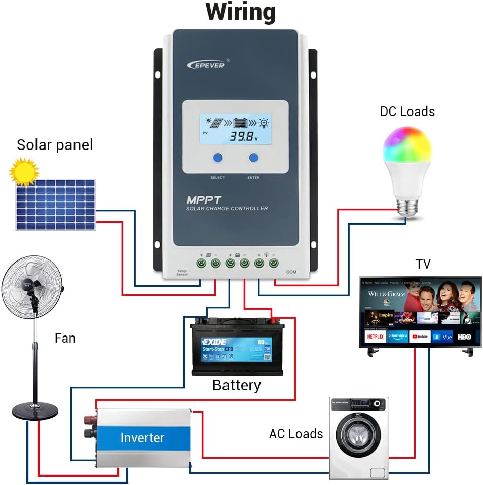
3.2 Schéma de câblage
Connect the components in the specified order to prevent damage. The connection order is: Battery → Solar Panel → Load. The disassembly order is the reverse: Load → Solar Panel → Battery.
3.3 Communication Ports and Accessories
The controller features various ports for enhanced monitoring and control.
- Capteur de température à distance (RTS) : Connect the RTS300R47K3.81A to the designated port for accurate battery temperature compensation. The standard cable length is 3m.
- Port de communication RS485 : This RJ45 port allows connection to various accessories for monitoring and parameter setting.
3.4 étapes d'installation
- Fixez solidement la manette à l'aide des trous de fixation prévus à cet effet.
- Raccordez la batterie aux bornes de la manette. Veillez à respecter la polarité.
- Connect the solar panel to the controller's solar panel terminals. Ensure correct polarity.
- Connect the DC loads to the controller's load terminals. Ensure correct polarity.
- Connect the temperature sensor probe to the controller.
3.5 Video: Unboxing and Installation
Watch this video for a visual guide on unboxing and installing the EPEVER Tracer-AN controller and its accessories.
4. Mode d'emploi
This section covers basic operation and how to configure essential settings on your controller.
4.1 Mode de commande manuelle
The controller supports manual control of the load. Press the 'ENTER' button to toggle the load on or off.
4.2 Setting the Battery Type
It is essential to set the correct battery type for optimal charging and battery longevity. The controller supports various battery types including Sealed (default), Gel, Flooded, and different Lithium battery configurations.
Pour définir le type de batterie :
- Press and hold the 'ENTER' button for 5 seconds when the battery voltage interface is displayed.
- Press the 'SELECT' button when the battery type interface is flashing to cycle through available battery types.
- Press the 'ENTER' button to confirm your selection.
4.3 Setting the Load Mode
The load working mode determines how the connected DC loads operate. Options include Light ON/OFF, various timer settings, test mode, and manual mode.
To set the load mode:
- Press and hold the 'ENTER' button for 5 seconds when the load mode interface is displayed.
- Press the 'SELECT' button when the load mode interface is flashing to cycle through available modes.
- Press the 'ENTER' button to confirm your selection.
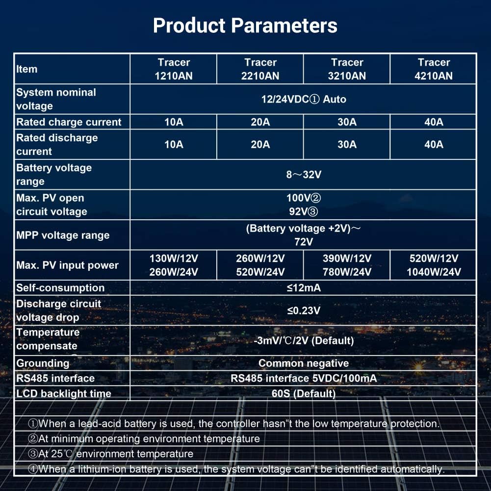
5. Spécifications
Below are the technical specifications for the Tracer1210AN MPPT Solar Charge Controller.
| Paramètre | Value (Tracer1210AN) |
|---|---|
| Volume nominal du systèmetage | 12 / 24VDC automatique |
| Courant de charge nominal | 10A |
| Courant de décharge évalué | 10A |
| Vol batterietaget gamme | 8~32V |
| Max. Volume de circuit ouvert PVtage | 100V (à une température ambiante de 25°C) |
| Vol MPPtaget gamme | Vol batterietage +2V ~ 72V |
| Puissance d'entrée PV max. | 130 W/12 V, 260 W/24 V |
| Autoconsommation | ≤12mA |
| Volume du circuit de déchargetage Déposez | ≤0.23V |
| Temperature Compensate | -3 mV/°C/2 V (par défaut) |
| Mise à la terre | Négatif commun |
| Interface RS485 | 5VDC / 100mA |
| Durée du rétroéclairage de l'écran LCD | 60S (par défaut) |
6. Accessoires
The EPEVER Tracer1210AN controller is often bundled with or compatible with several accessories to enhance its functionality.
- Compteur à distance MT50 : This remote meter can display various operating data and fault information. It features easy-to-operate buttons and a clear numeric display. It is used for monitoring and setting controller parameters.

Figure 6.1 : The MT50 Remote Meter, used for monitoring and configuring the solar charge controller. - Capteur de température à distance (RTS300R47K3.81A) : Acquires battery temperature for accurate temperature compensation of control parameters. The standard length of the cable is 3m.
- Câble USB vers RS485 (CC-USB-RS485-150U) : Used to connect the controller to a PC for monitoring and setting parameters via Solar Station PC software. The cable length is 1.5m.
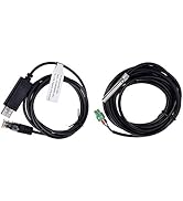
Figure 6.2 : The Remote Temperature Sensor (RTS) and the USB to RS485 communication cable. - OTG Cable (OTG-12CM): Used to connect a mobile communication cable to achieve real-time monitoring and parameter modification via a mobile APP.
- Adaptateur série WiFi (eBox-WiFi-01) : Allows monitoring and setting parameters via mobile APP software through WiFi signals.
- Adaptateur RS485 vers Bluetooth (eBox-BLE-01) : Enables monitoring and setting parameters via mobile APP software through Bluetooth signals.
- Enregistreur (eLOG01) : Records the operating status of the controller for later review.
7. Dépannage
If you encounter issues with your EPEVER Tracer1210AN controller, refer to the following common troubleshooting tips:
- Pas d'affichage sur l'écran LCD : Vérifiez les connexions de la batterie et assurez-vous que le volume de la batterietage est dans la plage de fonctionnement.
- Pas de recharge : Verify solar panel connections and ensure sufficient sunlight. Check for any shading on the solar panels. Confirm the battery type setting is correct.
- Chargement impossible : Check load connections and ensure the load mode is set correctly (e.g., Manual ON, Light ON/OFF). Verify that the battery voltage est au dessus du faible voltage seuil de déconnexion.
- Lecture de température inexacte : Ensure the Remote Temperature Sensor (RTS) is properly connected and positioned near the battery.
- Problèmes de communication : Check the RS485 cable connections to the remote meter, PC, or adapter. Ensure drivers are installed for PC communication.
For more detailed troubleshooting, consult the full product manual or contact EPEVER customer support.
8. Entretien
Un entretien régulier contribue à assurer la longévité et les performances optimales de votre régulateur de charge solaire.
- Propreté: Veillez à ce que la manette reste propre et exempte de poussière et de débris. Utilisez un chiffon sec pour la nettoyer.
- Relations: Vérifiez régulièrement le serrage et l'absence de corrosion de tous les raccords électriques. Des raccords desserrés peuvent provoquer une surchauffe et des dommages.
- Ventilation: Ensure adequate airflow around the controller to facilitate heat dissipation. Do not block the heat sink fins.
- État de la batterie : Surveiller le volume de la batterietage and health regularly. Ensure the battery type setting on the controller matches your battery.
- Mises à jour du micrologiciel : Vérifiez le fabricant website pour toute mise à jour du micrologiciel disponible afin d'améliorer les performances ou d'ajouter de nouvelles fonctionnalités.
9. Garantie et assistance
EPEVER products are designed for reliability and performance. For warranty information and technical support, please refer to the official EPEVER webconsultez votre site web ou contactez votre distributeur local.
You can also visit the official iSunergy store on Amazon for product information and support: iSunergy Amazon Store.