
1. Introduction
This instruction manual provides detailed guidance for the proper use and maintenance of your PETECHTOOL RJ45 Crimp Tool Set. This comprehensive kit is designed for various network wiring needs, including the creation and testing of custom-length Ethernet cables. It supports 8P8C RJ45 Cat6, Cat6a, Cat5e, Cat5 connectors and 6P6C RJ12 modular connectors (excluding AMP). Please read this manual thoroughly before operation to ensure safe and efficient use.
2. Consignes de sécurité
Always observe the following safety precautions when using the RJ45 Crimp Tool Set:
- Gardez les outils hors de portée des enfants.
- Portez un équipement de protection individuelle approprié, tel que des lunettes de sécurité, pour vous protéger contre les projections de débris.
- Assurez-vous que la zone de travail est bien éclairée et exempte d’obstructions.
- Do not use the tools for purposes other than their intended use.
- Handle sharp blades and crimping dies with care to prevent injury.
- The cable tester requires a 9-volt battery. Ensure correct polarity when inserting the battery. Do not mix old and new batteries.
- Disconnect power from any cables or devices before working on them.
3. Contenu du colis
Your PETECHTOOL RJ45 Crimp Tool Set includes the following components:
- 1 x RJ45 Pass-Through Crimp Tool
- 1 x Ethernet Cable Tester (Note: 9-volt battery not included)
- 1 x Mini pince à dénuder
- 50 x Cat6 Pass-Through RJ45 Connectors

Figure 3.1 : Plusview of the PETECHTOOL RJ45 Crimp Tool Set components.
4. Installation
4.1. Cable Tester Battery Installation
The Ethernet Cable Tester requires a 9-volt battery (not included) for operation.
- Locate the battery compartment on the back of the main (MASTER) unit of the cable tester.
- Faites glisser le couvercle de la batterie pour l'ouvrir.
- Insert a 9-volt battery, ensuring correct polarity (+ and - terminals).
- Fermez soigneusement le couvercle de la batterie.

Figure 4.1: Cable tester with battery compartment open, indicating the need for a 9V battery.
5. Mode d'emploi
5.1. Using the RJ45 Crimp Tool
The RJ45 Crimp Tool is designed for stripping, cutting, and crimping Ethernet and telephone cables. It features dedicated slots for 8P8C (RJ45) and 6P6C (RJ11/RJ12) connectors, along with a stripping slot for round cables and a sharp cutting blade.
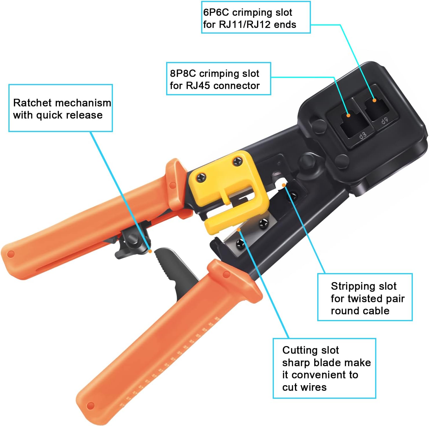
Figure 5.1 : Détaillé view of the crimp tool's functional areas.

Figure 5.2: Demonstrating the stripping, cutting, and crimping capabilities of the tool.
5.1.1. Crimping an RJ45 Connector (Pass-Through Method)
Follow these steps to create a custom-length Ethernet cable using the pass-through method:

Figure 5.3: Step-by-step guide for RJ45 pass-through crimping.
- Déverrouiller l'outil : First, press down on the handle to unlock the crimp tool.
- Dénuder la gaine du câble : Insert the Ethernet cable into the stripping slot and rotate the tool to strip approximately 1 inch (2.5 cm) of the outer jacket from the end of the cable.
- Supprimer l'excédent : Carefully cut off any small plastic or fiber strands that may be present after stripping.
- Démêler et arranger les fils : Untwist the individual twisted pairs and straighten the wires. Arrange them according to the T568A or T568B wiring standard (most common is T568B: Orange/White, Orange, Green/White, Blue, Blue/White, Green, Brown/White, Brown).
- Cut Wires Flat: Use the cutting blade on the crimp tool to cut the arranged wires flat and even, ensuring they are all the same length.
- Insérez les fils dans le connecteur : Carefully insert the straightened and cut wires into the RJ45 pass-through connector. Push them through until the wire ends emerge from the pins at the front of the connector. Ensure each wire is in its correct channel and fully extended.
- Insert Connector into Crimping Slot: Place the RJ45 connector, with the wires fully inserted, into the 8P8C crimping slot of the tool.
- Sertir le connecteur : Firmly squeeze the crimper's handles down until you can no longer go any further. The tool's ratchet mechanism will ensure a complete crimp and trim the excess wires protruding from the front of the pass-through connector.
- Vérifier: An Ethernet cable is now completed. Proceed to test the cable using the Ethernet Cable Tester.

Figure 5.4: Pass-through crimping tool in action.
5.2. Using the Ethernet Cable Tester
The Ethernet Cable Tester is used to verify the continuity and correct wiring of RJ45 (8P8C) and RJ11/RJ12 (6P6C) cables. It consists of a MASTER unit and a REMOTE unit.

Figure 5.5: Ethernet Cable Tester interface.
- Câble de connexion : Plug one end of the Ethernet or telephone cable into the appropriate port (RJ45 or RJ11) on the MASTER unit and the other end into the corresponding port on the REMOTE unit.
- Mise sous tension : Slide the power switch on the MASTER unit to either "ON S" (Slow Test) or "ON" (Quick Test).
- Observer les LED : The LED indicators (1 to 8 and G for ground/shield) on both the MASTER and REMOTE units will light up sequentially.
- Interpréter les résultats :
- Connexion normale : LEDs on both units will illuminate in the same sequence (1-2-3-4-5-6-7-8-G).
- Circuit ouvert: If a specific LED on either unit does not light up, it indicates an open circuit (broken wire) for that particular pin.
- Court-circuit: If multiple LEDs light up simultaneously or in an incorrect sequence, it indicates a short circuit between wires.
- Fils croisés : If the sequence of lights is different between the MASTER and REMOTE units (e.g., MASTER shows 1-2-3, REMOTE shows 1-3-2), it indicates crossed wires.
- Éteindre: After testing, slide the power switch to "OFF" to conserve battery life.
6. Entretien
- Nettoyage: Wipe the tools with a clean, dry cloth after each use to remove dust and debris. Do not use abrasive cleaners or solvents.
- Lubrification: Periodically apply a small amount of light machine oil to the moving parts of the crimp tool to ensure smooth operation.
- Stockage: Store the tools in a dry, cool place, away from direct sunlight and moisture, to prevent rust and damage.
- Remplacement de la batterie : If the cable tester's LEDs become dim or do not light up, replace the 9-volt battery. Remove the battery if the tester will not be used for an extended period.
7. Dépannage
| Problème | Cause possible | Solution |
|---|---|---|
| Crimp tool not cutting wires cleanly. | La lame est émoussée ou endommagée. | Inspect the blade. If dull, consider replacing the tool or seeking professional sharpening if possible. Ensure wires are properly aligned before cutting. |
| RJ45 connector not crimping properly. | Wires not fully inserted; incorrect connector type; insufficient pressure. | Ensure wires are pushed all the way through the pass-through connector. Verify you are using the correct 8P8C connector. Apply firm, even pressure until the ratchet mechanism completes its cycle. |
| Cable tester LEDs do not light up. | No battery; dead battery; incorrect battery polarity; faulty switch. | Install a fresh 9-volt battery. Check battery polarity. Ensure the power switch is fully in the "ON" or "ON S" position. |
| Cable tester shows incorrect wiring (open/short/crossed). | Improper crimp; damaged cable; incorrect wiring standard. | Re-crimp the connector, ensuring all wires are correctly seated and crimped. Inspect the cable for physical damage. Verify the wiring standard (T568A/T568B) was followed consistently on both ends. |
8. Spécifications
| Fonctionnalité | Détail |
|---|---|
| Marque | OUTIL PETECH |
| Numéro de modèle | RJ45 Crimp Tool Set |
| Compatibilité | 8P8C RJ45 (Cat6, Cat6a, Cat5e, Cat5), 6P6C RJ12 modular connectors |
| Matériel | Stainless Steel (Tool Body), Alloy Steel (Handle) |
| Couleur | Orange Crimp Tool Kit |
| Poids de l'article | 1.59 livres |
| Dimensions du colis | 9.21 x 4.84 x 2.05 pouces |
| Cable Tester Power Source | 1 x 9-volt battery (not included) |
| Composants inclus | RJ45 Crimper, Ethernet Cable Tester, Mini Wire Stripper, 50 Cat6 Connectors |
| Code UPC | 785471962667 |
9. Garantie et assistance
For any problems or questions regarding your PETECHTOOL RJ45 Crimp Tool Set, please contact the manufacturer directly. The manufacturer is committed to providing prompt assistance and the best possible solution to ensure customer satisfaction.
Please refer to your purchase documentation or the official PETECHTOOL webConsultez le site pour connaître les conditions de garantie spécifiques et les coordonnées.