1. Introduction
The Yaxun YX-9205 Digital Multimeter is a versatile and reliable instrument designed for measuring various electrical parameters. It is suitable for professional electricians, hobbyists, and students for testing and troubleshooting electronic circuits and devices. This manual provides essential information for safe and effective operation of your multimeter.
2. Consignes de sécurité
Always observe safety precautions when using any electrical testing equipment. Failure to do so may result in injury or damage to the multimeter or the equipment under test.
- Vérifiez que le multimètre est en bon état de fonctionnement avant utilisation.
- Ne pas appliquer voltage ou courant qui dépasse les limites maximales spécifiées pour chaque plage.
- Débranchez toujours les cordons de test du circuit avant de modifier les fonctions ou les plages de mesure.
- Soyez prudent lorsque vous travaillez avec des volumestages au-dessus de 30 V CA RMS, 42 V crête ou 60 V CC, car ceux-ci présentent un risque de choc électrique.
- Remplacez la pile lorsque le voyant de pile faible s'allume afin de garantir des mesures précises.
- N’utilisez pas le multimètre dans des atmosphères explosives ou en présence de gaz ou de poussières inflammables.
- Gardez vos doigts derrière les barrières de la sonde pendant les mesures.
3. caractéristiques du produit
The Yaxun YX-9205 Digital Multimeter offers a range of functions and features for comprehensive electrical testing:
- Multi-scale measurements for various electrical parameters.
- Mesure le volume CCtage, Vol ACtage, DC Current, AC Current, Resistance, Capacitance, Diode, and Continuity.
- Transistor hFE gain test function.
- Large LCD display with 4 digits, maximum reading 1999.
- Fonction de maintien des données pour figer les valeurs affichées.
- Fonction d'arrêt automatique pour économiser la batterie.
- Audible continuity signal.
- Indicateur de batterie faible.
- Integrated kickstand for convenient viewing.
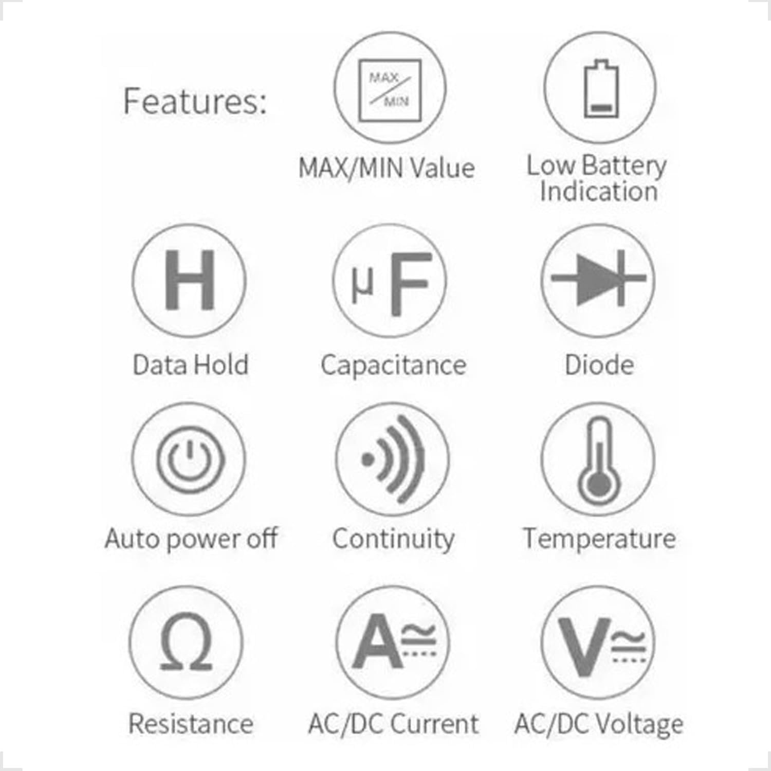
Figure 3.1: Feature Icons. This image displays a set of icons illustrating the key functions and capabilities of the Yaxun YX-9205 Digital Multimeter, such as data hold, capacitance measurement, diode testing, and auto power off.
4. Contenu du colis
Vérifiez que tous les éléments sont présents dans votre colis :
- Yaxun YX-9205 Digital Multimeter
- Cordons de test (rouge et noir)
- 9V Battery (6F22 type)
- Temperature Probe (K-type thermocouple, if included)
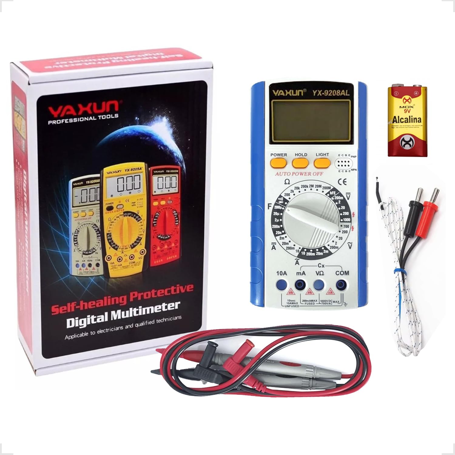
Figure 4.1: Package Contents. This image shows the Yaxun YX-9205 Digital Multimeter, along with its included red and black test leads and a 9V battery.
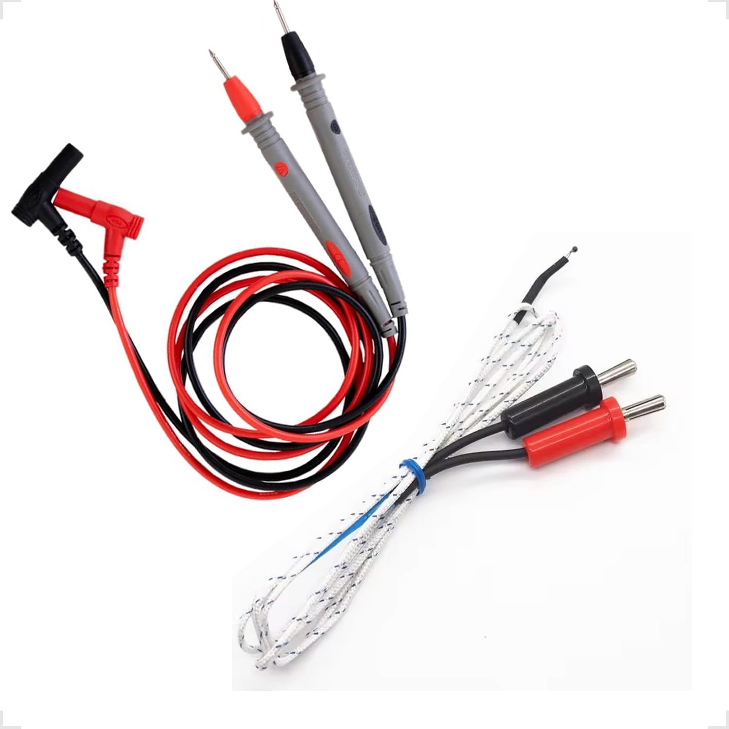
Figure 4.2: Test Leads and Temperature Probe. This image details the included red and black test leads, essential for making electrical measurements, and a white temperature probe.
5. Installation
5.1 Installation de la batterie
The multimeter requires a 9V battery for operation. Follow these steps to install or replace the battery:
- Assurez-vous que le multimètre est éteint et que les cordons de test sont déconnectés.
- Repérez le couvercle du compartiment à piles à l'arrière du multimètre.
- Use a screwdriver to remove the screw securing the cover, then lift the cover off.
- Connectez la pile 9V au clip de la pile en respectant la polarité.
- Placez la pile dans le compartiment et remettez le couvercle en place en le fixant avec la vis.

Figure 5.1: Battery Compartment. This image shows the rear of the multimeter, highlighting the battery compartment cover, which needs to be opened for battery installation or replacement.
5.2 Connexion des cordons de test
Un branchement correct des cordons de test est crucial pour des mesures précises et sûres :
- Insérez le fil de test noir dans la prise « COM » (Commun).
- Pour la plupart des volstagPour les mesures de résistance et de continuité, insérez le fil de test rouge dans la prise « VΩmA ».
- For high current measurements (up to 10A), insert the red test lead into the "10A" jack. Ensure the rotary switch is set to the appropriate current range.
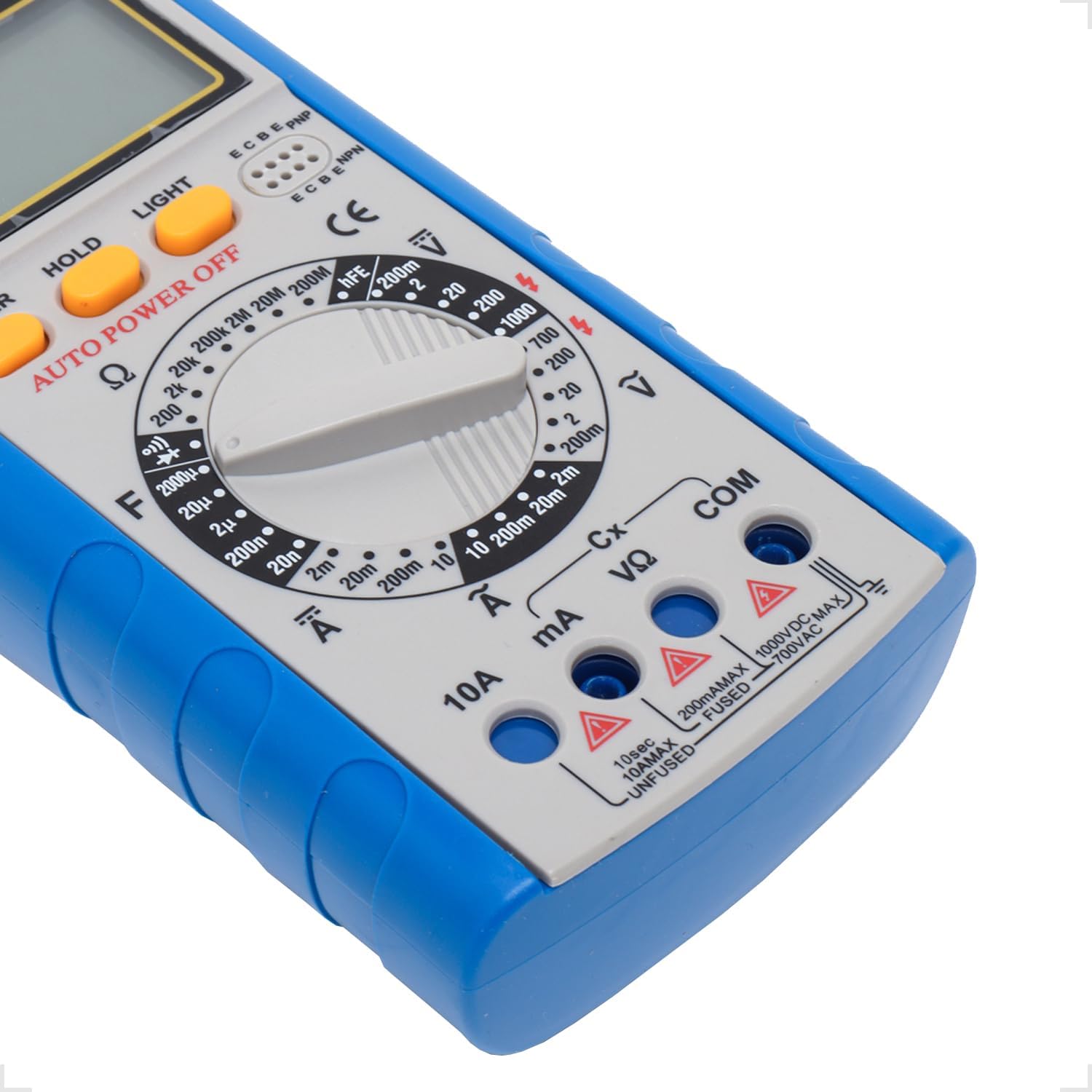
Figure 5.2: Input Jacks. This image provides a detailed view of the multimeter's input jacks: COM (common), VΩmA (for voltage, resistance, and low current), and 10A (for high current measurements).
5.3 Utilisation de la béquille
The multimeter features a built-in kickstand for hands-free operation and improved viewing angle. Simply pull out the kickstand from the back of the unit to deploy it.

Figure 5.3: Multimeter with Kickstand. This image shows the multimeter standing upright with its integrated kickstand extended, providing a stable and convenient viewangle d'inclinaison pendant l'utilisation.
6. Mode d'emploi
6.1 Fonctionnement général
The YX-9205 multimeter is operated primarily using the rotary switch and function buttons.
- Commutateur rotatif : Selects the desired measurement function (e.g., VDC, VAC, ADC, AAC, Ω, F, Diode, Continuity, hFE).
- Bouton d'alimentation: Allume ou éteint le multimètre.
- Bouton MAINTENIR : Fige l'affichage actuel. Appuyez de nouveau pour relâcher.
- Bouton LUMIÈRE : Active le rétroéclairage de l'écran pour une meilleure visibilité en conditions de faible luminosité.

Figure 6.1 : Panneau de commande. Cette image fournit une vue détaillée view of the multimeter's main controls, including the central rotary switch for function selection and the Power, Hold, and Light buttons.
6.2 Mesure du volume CCtage (VCC)
- Insert the black lead into the COM jack and the red lead into the VΩmA jack.
- Tournez le commutateur rotatif sur le volume CC souhaitétagla plage (par exemple, 200 mV, 2 V, 20 V, 200 V, 1000 V). Si le voltage étant inconnu, commencez par la plage la plus élevée et diminuez-la au besoin.
- Connectez les sondes de test aux bornes du composant ou du circuit à mesurer, en respectant la polarité.
- Lire le voltage valeur sur l'écran LCD.
6.3 Mesure du volume CAtage (VAC)
- Insert the black lead into the COM jack and the red lead into the VΩmA jack.
- Tournez le commutateur rotatif sur le volume CA souhaitétagla plage (par exemple, 200 mV, 2 V, 20 V, 200 V, 700 V). Si le voltage est inconnu, commencez par la plage la plus élevée.
- Connect the test probes across the component or circuit to be measured. Polarity is not critical for AC voltage.
- Lire le voltage valeur sur l'écran LCD.
6.4 Measuring DC Current (ADC)
Caution: Always connect the multimeter in series with the circuit when measuring current. Never connect it in parallel across a voltage source, as this can damage the multimeter and the circuit.
- Determine the expected current. For currents up to 200mA, use the VΩmA jack for the red lead. For currents up to 10A, use the 10A jack for the red lead. The black lead always goes into COM.
- Turn the rotary switch to the appropriate DC Current range (e.g., 2mA, 20mA, 200mA, 10A).
- Open the circuit where current is to be measured and connect the test leads in series.
- Lire la valeur actuelle sur l'écran LCD.
6.5 Measuring AC Current (AAC)
Caution: Always connect the multimeter in series with the circuit when measuring current. Never connect it in parallel across a voltage source, as this can damage the multimeter and the circuit.
- Determine the expected current. For currents up to 200mA, use the VΩmA jack for the red lead. For currents up to 10A, use the 10A jack for the red lead. The black lead always goes into COM.
- Turn the rotary switch to the appropriate AC Current range (e.g., 2mA, 20mA, 200mA, 10A).
- Open the circuit where current is to be measured and connect the test leads in series.
- Lire la valeur actuelle sur l'écran LCD.
6.6 Mesure de la résistance (Ω)
Caution: Ensure the circuit or component under test is completely de-energized before measuring resistance. Disconnect power and discharge any capacitors.
- Insert the black lead into the COM jack and the red lead into the VΩmA jack.
- Turn the rotary switch to the desired Resistance range (e.g., 200Ω, 2kΩ, 20kΩ, 200kΩ, 2MΩ, 20MΩ, 200MΩ).
- Connectez les sondes de test aux bornes du composant à mesurer.
- Lisez la valeur de résistance sur l'écran LCD.
6.7 Measuring Capacitance (F)
Caution: Ensure capacitors are fully discharged before testing. High voltage capacitors can store dangerous charges.
- Insert the black lead into the COM jack and the red lead into the VΩmA jack.
- Turn the rotary switch to the Capacitance (F) function and select the appropriate range (e.g., 20nF, 200nF, 2µF, 20µF, 200µF).
- Connectez les sondes de test aux bornes du condensateur.
- Lire la valeur de capacité sur l'écran LCD.
6.8 Test de diode
- Insert the black lead into the COM jack and the red lead into the VΩmA jack.
- Tournez le commutateur rotatif sur le symbole de la diode.
- Connectez la sonde rouge à l'anode et la sonde noire à la cathode de la diode. L'écran affichera la tension directe.tagchute de tension (généralement de 0.5 V à 0.8 V pour les diodes au silicium).
- Reverse the probes. The display should show 'OL' (Open Loop) for a good diode. A reading in both directions or 'OL' in both directions indicates a faulty diode.
6.9 Essai de continuité
- Insert the black lead into the COM jack and the red lead into the VΩmA jack.
- Turn the rotary switch to the Continuity symbol (often shared with the Diode function).
- Connectez les sondes de test aux bornes du circuit ou du composant.
- Si la résistance est inférieure à environ 50 Ω, un signal sonore retentit pour indiquer la continuité. La valeur de la résistance s'affiche également.
6.10 Test du gain en courant (hFE) des transistors
- Tournez le commutateur rotatif sur la position hFE.
- Identifiez si le transistor est de type NPN ou PNP.
- Insert the transistor's emitter, base, and collector leads into the corresponding holes in the hFE socket on the multimeter.
- Lisez la valeur hFE (gain en courant continu) sur l'écran LCD.
7. Spécifications
| Paramètre | Gamme | Précision |
|---|---|---|
| Vol CCtage | 200 mV, 2 V, 20 V, 200 V, 1000 XNUMX V | ±(0.5 % + 1 chiffres) |
| Vol ACtage | 200 mV, 2 V, 20 V, 200 V, 700 XNUMX V | ±(0.8% + 3 chiffres) |
| Courant continu | 2 mA, 20 mA, 200 mA, 10 A | ±(0.5 % + 1 chiffres) |
| Courant alternatif | 2 mA, 20 mA, 200 mA, 10 A | ±(1.0% + 3 chiffres) |
| Résistance | 200Ω, 2kΩ, 20kΩ, 200kΩ, 2MΩ, 20MΩ, 200MΩ | ±(0.8 % + 1 chiffres) |
| Capacitance | 20nF, 200nF, 2µF, 20µF, 200µF | ±(4.0% + 3 chiffres) |
| Afficher | 1999 counts, 60 x 31.5mm LCD | |
| Alimentation électrique | 9V Battery (6F22) | |
| Dimensions (L x l x H) | 180 x 86 x 35 mm | |
8. Entretien
8.1 Nettoyage
Pour nettoyer le multimètre, essuyez le boîtier avec un chiffon humide.amp cloth and a mild detergent. Do not use abrasives or solvents. Ensure the multimeter is completely dry before use.
8.2 Remplacement de la batterie
When the low battery indicator appears on the display, replace the 9V battery as described in the 'Battery Installation' section (5.1). A weak battery can lead to inaccurate readings.
8.3 Remplacement du fusible
Caution: Always disconnect test leads and turn off the multimeter before replacing the fuse. Use only fuses of the specified type and rating.
If the multimeter fails to measure current, the fuse may be blown. To replace the fuse:
- Éteignez le multimètre et débranchez tous les cordons de test.
- Ouvrez le couvercle du compartiment de la batterie comme décrit dans la section 5.1.
- Retirez soigneusement l'ancien fusible.
- Install a new fuse of the correct type and rating (e.g., F200mA/250V for mA ranges, F10A/250V for 10A range). Refer to the markings near the fuse holder if available.
- Replacez le couvercle du compartiment des piles et fixez-le avec la vis.
9. Dépannage
| Problème | Cause possible | Solution |
|---|---|---|
| Aucun affichage ou affichage faible | Batterie morte ou faible | Remplacez la pile 9V. |
| Lectures incorrectes | Incorrect range selected, poor lead connection, weak battery | Select the correct range, ensure leads are firmly connected, replace battery. |
| Aucune mesure actuelle | Blown fuse, incorrect lead connection | Check and replace fuse if necessary, ensure leads are in correct current jacks and connected in series. |
| « OL » (Surcharge) affiché | Measurement exceeds selected range, open circuit | Select a higher range, check for open circuit. |
10. Garantie et assistance
This Yaxun YX-9205 Digital Multimeter is designed for reliability and performance. For specific warranty information, please refer to the purchase documentation or contact your retailer. For technical support or inquiries, please reach out to the Yaxun customer service department or your local distributor.